Difference between revisions of "705 - Foundation Piling"
JohnsonN23 (talk | contribs) m (→Ordering Pile Driving Charts: relink) |
|||
| Line 402: | Line 402: | ||
====[[#Ordering Pile Driving Charts|Ordering Pile Driving Charts]]==== | ====[[#Ordering Pile Driving Charts|Ordering Pile Driving Charts]]==== | ||
| − | When pile charts are needed immediately, submit MDOT [http:// | + | When pile charts are needed immediately, submit MDOT [http://mdotjboss.state.mi.us/webforms/GetDocument.htm?fileName=1956.pdf form 1956 – LRFD Pile Driving and Equipment Data] to the [http://www.michigan.gov/mdot/0,4616,7-151-9623_26663_27303-269622--,00.html Geotechnical Services Section] and [http://www.michigan.gov/mdot/0,4616,7-151-9623_26663_56139_56173---,00.html Bridge Field Services] for review and creation of pile driving charts. |
{{top}} | {{top}} | ||
Revision as of 09:19, 14 February 2017
GENERAL
Foundation piles are typically steel H sections or cast-in-place (CIP) concrete in steel shells. Occasionally the plans specify treated timber piles. Foundation piles provide support for the bridge or structure when the existing soils do not provide adequate bearing capacity to support a spread footing.
Foundation piles may be straight or battered. Generally, piles are battered no flatter than 3V:1H. This can be increased to 2.5V:1H or even 2V:1H where soil conditions are not good enough to provide sufficient lateral pile resistance and this will be noted on the plans. It can be difficult to maintain driving accuracy when the batter is flatter than 3V:1H.
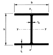
The most common steel section used for piles is the HP section. For example, for a HP 12X53 section, H stands for the “section shape”, P stands for “pile”, the 12 represents the height, h, in inches, and the 53 represents the unit weight per foot of material. Figure 1 shows the typical HP section configuration.
Steel pipe piles for CIP piles are typically designated by the outer radius, and the pipe wall thickness. All pipe pile used on MDOT projects shall be seamless, meaning the welds shall be done from the electric resistance, or fusion welding processes.
It should be noted that static analysis is performed during the design phase of the project to determine the appropriate design pile section, design pile lengths, design pile tip elevations. These values are shown on the plans, and are used to determine the estimated pile lengths, and estimated pile tip elevations.
Steel piles brought to the site can be new or used, however, used piles must be in good condition, and the Contractor must provide mill test reports, and required Buy America certification. Contact the Geotechnical Services, or the Bridge Field Services areas for any questions regarding acceptable condition.
Piles are to be stored off the ground on cribbing when on site. The following should be checked prior to incorporation into the project:
- Check for bending or distortion of steel piles
- Ensure steel piles do not have any section loss, drilled holes, or stray weld strikes
- Ensure dirt, water or other deleterious materials do not enter steel shells for CIP piles
- Timber piles are to be closely stacked together to prevent sagging
MATERIALS
Timber Piles
Ensure timber piles are structural timber or lumber of the material grade as called for on the plans, and per subsection 912.05 of the Standard Specifications for Construction.
Ensure piles are treated with preservative per subsection 912.06 of the Standard Specifications for Construction.
Steel Piles and CIP Pile Shells
Ensure steel piles, steel pile shells for CIP piles, and pile points are of the material grade and yield strength as called for on the plans, and per 12SP906(A). Check the plans and specifications for galvanizing requirements. If required, ensure the Contractor provides proper documentation of galvanizing
Concrete
Ensure concrete for CIP piles is Concrete, Grade S1, per subsection 701 of the Standard Specifications for Construction.
CONSTRUCTION
Equipment
Ensure the contractor is using appropriate equipment to drive production piles and test piles without damaging them. The following pile driving equipment is subject to the approval of the MDOT Geotechnical Services Section area based on the pile driveability analysis:
- Pile Driving Hammer
- Hammer cushion
- Pile helmet
- Pile cushion
- Any other pertinent equipment
Submit MDOT form 1956 – LRFD Pile Driving and Equipment Data to the Geotechnical Services Section and Bridge Field Services for review and creation of pile driving charts.
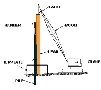
See Figure 2 for typical pile driving equipment set up with the hammer supported in swinging leads:
Pile driving equipment is to be selected such that the piles are installed at a rate of 2 blows per inch to 10 blows per inch.
Pile stresses shall not exceed the values shown in Table 705-1 of the Standard Specifications for Construction.
The Geotechnical Services Section will predict pile stresses using the wave equation analysis, based on hammer efficiencies shown in Table 705-2 of the Standard Specifications for Construction.
The pile driving system proposed by the Contractor is subject to approval from the Geotechnical Services Section.
Air (steam), diesel or hydraulic hammers can be used.
Drop Impact Hammers
Drop impact hammers are gravity type hammers, where a weight is simply lifted and released. Drop hammers may be prohibited on timber piles, check the plans and specifications for any restrictions.
Drop Impact hammers are not to be used for piles where the required nominal pile driving resistance exceeds 200 kips.
Single Acting (Air) Hammers
These hammers are powered by compressed air or steam provided from an air compressor or steam boiler.
The hammer is generally assumed to be developing its rated energy when it is striking the number of blows per minute as shown in the manufacturer's catalog. If a hammer will not develop its rated number of blows at bearing, the inspector should suspend driving operations. In most cases, the problem is caused by insufficient pressure at the hammer because of line losses caused by leaky connections, excessive line length, etc.
Closed-Top Type Diesel Hammers
Closed ended hammers are closed at the top, and contain a bounce chamber to throw the ram back down upon rebound.
The maximum rated energy should be used in calculating bearing only when the hammer is on the verge of floating on top of the pile. If this floating action is unattainable, the Contractor should furnish an instrument to measure the bounce chamber pressure and resulting hammer output, and use the manufacturers chart to correlate pressure reading with the energy being delivered by the hammer.
Open-Type Diesel Hammers
These are the most common. Open ended hammers are open at the top, allowing observation of the ram going up and down. Diesel fuel is ignited, which thrusts the ram upward, followed by the ram falling and striking the pile top.
Hydraulic Impact Hammers
Hydraulic hammers are fueled by a hydraulic unit, with the hammer energy correlated through pressure readings.
A wave equation analysis must be performed by the Contractor, and check by the Geotechnical Services area to determine the nominal driven bearing of the pile
Non-Impact Hammers
Vibratory equipment may be used for sticking piles, but not for advancing piles. Do not use vibratory hammers, driving aids, followers or prebored holes unless approved by the Geotechnical Services area.
Hammer Cushion
Hammer cushions are to be used to prevent damage to the pile during driving by dampening reflected forces, and ensuring a uniform strike at the top of the pile. Certain hammer types are designed for use without a cushion.
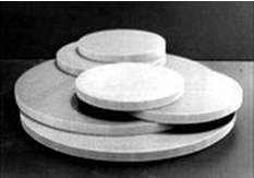
Wood, elastomerics, wire rope or asbestos cannot be used, as these materials tend to deform during driving. Ensure a striker plate is used on top of the cushion to ensure uniform compression of the material. Modern hammer cushions use phenolic laminates (synthetic resin), or special alloyed nylon blocks with aluminum layers. See Figure 3 for typical nylon hammer cushions:
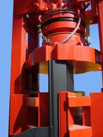
Inspect the cushion before production pile driving commences, and inspect after 100 hours of operation, or prior to driving at each subsequent structure. The striker plate portion of the helmet needs to be remove to gain access to the cushion. See Figure 4 for a typical helmet and cushion configuration. Ensure the contractor replaces the cushion once the thickness is reduced more than 25% of the original thickness.
Helmet
Hammer helmets distribute the hammer blow uniformly and concentrically to the pile top. Ensure the helmet surface in contact with the pile is smooth, and aligned with the hammer base and the pile top.
Ensure the helmet is guided with the leads, and not allowed to swing freely.
For timber piles, ensure the helmet does not exceed the pile top by more than 2 inches. The Contractor shall trim the pile top to fit into the helmet.
Pile Cushion
Pile cushions are only required when CIP concrete piles require redriving after the concrete placement and curing.
Leads
Leads are typically box shaped frames used align the pile and hammer in the appropriate position throughout the driving operation, and maintain hammer and pile alignment to ensure concentric impact on the top of the pile during striking.
Leads used for pile driving are either swing or fixed-type. Ensure swing type leads contain a pile gate at the bottom. Ensure leads of appropriate length to eliminate the need for followers.
The Contractor should be encouraged to use the fixed-type wherever possible as they do a better job of holding the pile in position.
Followers
Pile followers are essentially extensions of the piles being driven allowing the piles to be driven at a higher elevation. Followers are only to be used with approval from the Geotechnical Services Section, as there is uncertainty as to how much hammer energy is transferred across the joint between the follower and the production pile.
Test Piles
When test piles are shown in the plans and specifications, the pile lengths shown on the plans are for estimating purposes only. There are typically two test piles per substructure unit.
Test piles should be driven prior to the production piling so the results can be used as a guide in ordering piles and driving all production piling. Contractors typically place test and production piling orders simultaneously due to mill and fabricator schedules.
Ensure test piles are driven to the minimum pile length shown on the plans, practical refusal (110% of nominal), whichever is greater.
To track test pile driving information, use MDOT form 1157L – TEST PILE RECORD, LRFD.
Test Pile Penetration Observations
It is important at the start of the blow count to reference the pile to some fixed object, preferably the leads, providing they are not reset during the observation period.
Reference Stake
Driving a reference stake adjacent to the pile should be avoided because clay soil has the tendency to heave and sandy soil has the tendency to consolidate.
Soil heaving and consolidating soil would raise or lower the reference stake causing erroneous penetration readings affecting the recorded bearing.
Besides the penetration readings, the inspector will simultaneously record the distance the pile point is below cutoff. This is accomplished by having the piling marked off in 1 foot intervals starting from the point and referencing the piling marks to a grade stake set at cutoff elevation.
Restrike
Restriking is allowed for test piles only. If practical refusal cannot be achieved after driving 10 feet below the estimated pile tip elevation, and the resistance is at least 85% of the required nominal pile driving resistance, the Contractor may leave the piles to set up for 48 hours.
After the 48 hours waiting period, The Contractor may restrike the piles. Contact the Geotechnical Services area to determine the nominal pile driving resistance based on the number of blows necessary to advance the pile an additional 3 inches.
Ensure the hammer is warmed up with 25 blows.
Ensure the appropriate records for test piles are kept, including:
- Number of blows per inch for the driven length, and stroke height.
- As-driven length of test pile
- Cutoff elevation
- Penetration into the ground
- Number of splices
Ensure test piles not included in production pile locations are cutoff or pulled.
Pile Points
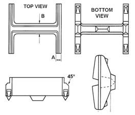
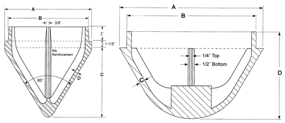
Check the plans and specifications to see if pile points are to be used. Pile points are welded to the driving end of HP, and CIP piles to aid in tough driving conditions and/or end bearing in rock. A typical HP pile point is shown in Figure 5 below. Typical pile points for CIP piles are shown in Figure 6 below:
Equipment Changes
All piles for a given foundation unit will be driven with the same hammer operated under the same conditions with the same cushion material as used to drive test piles. Changing hammers requires additional test pile driving at the Contractor’s expense.
Driving of Production Piles & Construction Inspection
To track pile driving operations, use MDOT form 1990 – COFFERDAM INSTALLATION, PILING PLACEMENT, AND TREMIE POUR INSPECTOR’S CHECKLIST, and MDOT form 1161L - FOUNDATION PILING RECORD, LRFD
Prior to Pile Driving
Prior to the start of driving and during the operation, check the plans and specifications, and pay close attention to all of the following:
- Ensure the proper orientation and layout of the pile. The contractor will do the actual layout. For example, on integral abutments with a single row of piles, the web of the pile is oriented perpendicular to the construction centerline of the bridge. This is also referred to orienting the pile about the weak axis of bending.
- Ensure all piles meet the material grade requirements as specified in the plans, and 12SP906(A).
- Review the Soil Borings and SPT Blow Count Data shown on the plans. Become familiar with the soil borings in the footing area. Be aware of potential hard layers above the estimated pile tip elevations that can give false bearing. These areas are typically underlain by unsuitable material.
- Review the plans and specifications for preboring requirements. If required, ensure holes are prebored to the elevations shown on the plans, and the hole diameter is 6 inches greater than the pile dimensions. Preboring also includes the following:
- Boring pile holes
- Disposal of excavated material
- Backfilling voids
- Installing and removing temporary casings
- Providing and disposing of drilling slurry
- Restriking completed piles within a radius of 20 feet
- Equipment operating costs, unless including in the Pile Driving Equipment, Furn pay item
- Ensure all excavation and embankment is complete to the bottom of substructure concrete elevation.
- If the Contractor is using a template, check the template dimension against the plan dimensions.
- Check to ensure that battered piles will clear the toe of any cofferdam sheet piling.
- On certain types of abutments an error in grade could easily result in the piling being too close to or possibly outside the wall forms.
During Pile Driving
- During construction, the nominal pile driving resistance is measured and verified during pile driving with the dynamic formula or dynamic testing methods
- Ensure the pile tops are square with the axis of the pile.
- If impenetrable obstructions are encountered during driving, direct the Contractor to remove and reuse the pile, or cut off and drive a new pile. Ensure the pile is cut to the lowest possible elevation, and drive another pile, adjusted laterally.
- Check the plans for design pile lengths (pile lengths shown on the plans), or estimated pile lengths (pile lengths shown on plans used as guide if the nominal pile driving resistance is shown on the plans.
- If the plans show design pile lengths, ensure piles are driven to the design pile tip elevations shown on the plans, unless driving operations attain absolute refusal (150% of the nominal pile driving resistance shown on the plans).
- If the plans show estimated pile lengths, install piles to a the following penetration:
- The nominal pile driving resistance equals at least the required nominal pile driving resistance; and
- The bottom of the pile is at or below the minimum pile penetration elevation shown on the plans.
- Ensure piles are not driven past absolute refusal unless Dynamic Testing is required. Any unnecessary production piling overdriving is to be avoided as it adds unnecessary project cost.
- Ensure completed piles are driven according to the following accuracy criteria:
- 1/4 inch per foot from vertical or batter line
- Pile cutoff location is within 6 inches from plan position unless noted on plans
- 9 inches between the edges of piles and the outline of the concrete forms
- Pile bents are to meet the tolerances as shown on the plans
- Pile cut off within 1”
- Do not allow the Contractor to laterally pull piles to correct misalignment, or splice subsequent piles to correct misalignment.
- Take level readings to measure pile heave after driving. If piles heave up during driving of adjacent piles, direct the Contractor to re-drive to the required bearing capacity or penetration elevation. For heaved CIP piles, ensure the concrete obtains its 28 day compressive strength prior to re-drive.
- For battered piles, ensure the piles are driven to the angle shown on the plans. Note that the hammer energy will need to be reduced to account for losses due to the inclination of the hammer. Check the batter with a carpenter’s level attached to the vertical side of the Contractor’s template.
If at any time, the nominal pile driving resistance cannot met, but minimum pile penetration is achieved, contact the Geotechnical Services area for guidance.
After Pile Driving
- Ensure battered piles are cut perpendicular to the axis of the pile, not parallel with finished grade.
- After driving CIP shell piling inspection will be done by using a mirror or light provided by the Contractor, suitable for illuminating the shell interiors. The shells will be free of bends, kinks or other deformations that would impair the completed pile strength.
- After driving the piling, piling tops will be immediately covered to keep out rain, sand, etc. The piling should be cut off within 1 inch of the specified elevation and filled with grade S1 concrete as soon as possible.
- Ensure any subsequent pile driving within a radius of 25 feet from concrete element pours are done after concrete has attained 75 percent of its design strength.
- Concrete should be cast in slowly so that an air pocket is not formed in the pile. An inspector should be present at all times during placement. No concrete will be placed in any pile until all piles within a 20 foot radius have been driven and accepted.
- For CIP piles, ensure concrete is placed per subsection 706.03.H of the Standard Specifications for Construction. Concrete in the pile shell’s upper third (not to exceed 25 feet) is to be vibrated by an approved method.
- Ensure the Contractor cleans the shells of CIP concrete piles where embedded 1 foot or more in structural concrete.
- Check for any heaved piles. Heaved piles are to be redriven, and will be paid for as extra work.
Defective Piles
Methods to correct piles damaged by internal defects, improper driving, driven below cutoff elevation, or driven outside of plan locations are as follows:
- Withdraw the pile and replace with a new, longer stick (if feasible).
- Drive a second pile adjacent to the defective pile (verify with Bridge Design, and the Geotechnical Services area).
- Splice or build up the pile, or extend a portion of the footing to properly embed the pile
Obstructions
Removal of obstructions that require special equipment or tools will be measured and paid for as extra work per subsection 109.05.D of the Standard Specifications or Construction. A budget amount will be established to pay for removing obstructions. If the Contractor and the Engineer cannot agree on a lump sum price, the Engineer will direct the work to be done on a force account basis.
Splicing
Steel piles and steel pile shells may be furnished in full length sections or the pile shells may be spliced according to the splicing method as shown on the plans. Note when pile splicers are not permitted in the plans.
Splices will be made according to 12SP705(A) – Pile Splicing and the Contractor shall submit a QA/QC plan in accordance with special provision 12SP705(B) – Quality Control Plan for Welding Foundation Splices. Welding is to be done by a certified welder qualified in the 2G position for welding the pile in the vertical position. If the piling is spliced while lying on the ground, the welder will also be qualified in the 3G position. Furnished pile less than 40 shall contain no more than 3 splices, and furnished pile greater than 40 feet shall contain no more than 4 splices.
All welded splices shall be done in accordance with the MDOT Field Manual for Pile Welding –. See this manual for more details
Welded
Welded splices for piles will be made only by qualified welders using E7015, E7016 or E7018 electrodes.
CIP Concrete Piles
Shells for CIP concrete piles will be spliced using a chill ring or other type backing detail as shown on the plans.
Steel Piles
Steel piles will be spliced as shown on the plans using preformed-preassembled bent plates or flat splice plates for pier piles, and other piles that are not considered primary members as called for on the plans. Pile acceptance is based on the Contractor’s conformance to their QA/QC plan, and can be visual.
Full penetration butt weld, or Complete Joint Penetration (CJP) welds are required for piles in integral abutments, and when otherwise defined as primary members on the plans. Pile acceptance for these members is based on 100% ultrasonic thickness testing (UT).
All splices require welding. Splicing devices which do not develop the full plan weld are not permitted.
Scarfing
Scarfing the upper splice length of the piles preparatory to butt welding will be done by a cutting torch using a guide to assure a smoother chamber. A maximum of 1/8 inch land (shoulder) will be retained. If the end of the driven length of pile is damaged during the driving operation, it must be trimmed.
Offhand Burning
Offhand burning will be permitted if trimming is minor. When it is necessary to cut a small section off the end of the driven pile length to square the end, burning must be done using a guide either clamped or tack welded in place. All adhering slag will be removed and the joint surfaces will be thoroughly cleaned by wire brushing before welding. A root opening of the butt joint will provide a 1/8 inch clear opening at the nearest point. When the 1/8 inch opening at the nearest point allows more than a ¼ inch opening at other points, correction will be made to provide the correct opening before welding. Beveling by cutting will be required for correcting openings wider than ¼ inch.
Root Opening
The root opening may be held by two wedges before tacking. The members to be welded will be brought into correct alignment along the pile length and held rigidly by clamps or by dogging. Clamps or dogs may be removed after tack welding sufficiently to hold the member in place.
Where the parts are restrained against bending due to eccentricity in alignment, an offset not exceeding 10 percent thickness of the thinner part joint, but no more than 1/8 inch may be permitted as a departure from the theoretical alignment. In correcting misalignment, the parts will not be drawn into a greater slope than ½ inch per foot. Offset measurement will be based upon the centerline of parts unless otherwise shown on the drawing.
The root pass will be a stringer bead, placed with sufficient amperage to fully penetrate through the joint. Passes will be made symmetrically and will alternate on both flanges to minimize distortion. After the face side of both flanges and web has been welded completely, a backing bead will be made on the opposite side.
DETERMINATION OF NOMINAL PILE RESISTANCE
The capacity of foundation piles is achieved through skin friction between the soil and the surfaces of the pile, tip capacity of the pile tip embedding into bedrock, or a combination of the two. The following methods are used to attain required nominal pile driving resistance:
- Piles are driven to the minimum pile penetration elevation, and nominal resistance, or
- Static load tests for piles with a nominal pile driving resistance greater than 600 kips, or
- Using the Dynamic Formula for production piles less than 600 kips nominal pile driving resistance, or
- Dynamic testing and analysis
A saximeter is to be used to verify blow counts, and the results compared to the dynamic analysis results. The saximeter works for several hammer types as follows:
- For open ended diesel hammers, the saximeter computes stroke and potential energy from the measured blows per minute. This information is then multiplied by the hammer weight to obtain the hammer energy.
- For other types of hammers, the Contractor is required to provide an electronic measuring device.
Static Load Test
For high capacity piles, < 600 kip nominal pile resistance, static load tests may be required. Load testing details will be in the plans and specifications. This generally involves the placement of large amounts of weight on a group of piles, and recording measurements on vertical displacements and deflections. The Geotechnical Services Section will approve the load test methods.
Dynamic Formula
The Dynamic Formula (FHWA Modified Gates Formula) is not to be used on piles with a required nominal pile driving resistance greater than 600 kips. Check the plans and specifications for dynamic testing with signal matching.
For battered piles, use a hammer energy reduction coefficient.
These formulas are applicable under the following conditions – Notice if these conditions are not met:
- Hammers and unrestricted free fall
- Pile tops are not broomed, crushed, or splintered
- The hammer exhibits no appreciable bounce after striking the pile
- Penetration is at a uniform or uniformly decreasing weight
Ordering Pile Driving Charts
When pile charts are needed immediately, submit MDOT form 1956 – LRFD Pile Driving and Equipment Data to the Geotechnical Services Section and Bridge Field Services for review and creation of pile driving charts.
