706 - Structural Concrete
GENERAL DESCRIPTION
The standard specifications contain details for Structural Concrete Construction.
Definitions and Terms
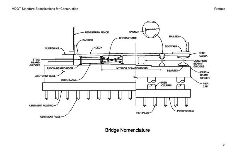
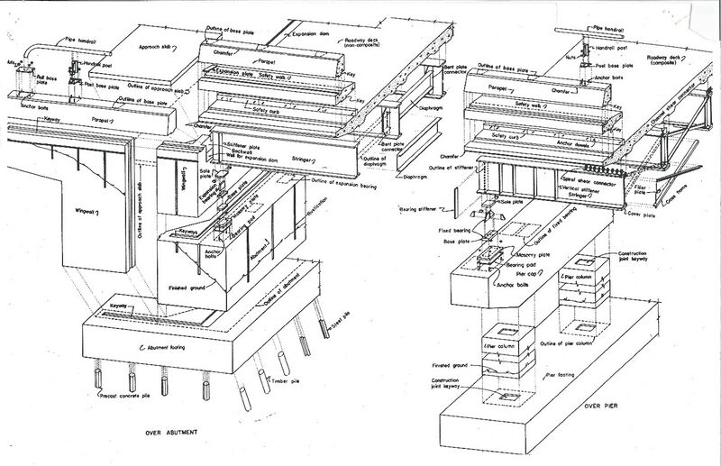
The following diagrams depict many common structural concrete bridge components:
MATERIALS
EQUIPMENT
Concrete placing equipment includes equipment for tremie pours, substructure placing equipment, concrete pumps, saws, bridge deck placing equipment, texturing equipment, concrete curing equipment, equipment for placing water repellant materials, and other miscellaneous equipment. Do not allow the Contractor to move the screed rails for the bridge deck finishing equipment to anywhere other than the fascia beams without contacting BoBS Construction Group.
PRECONSTRUCTION
CONSTRUCTION
False Decking
False decking design is the responsibility of the contractor, but the installation should be monitored for safety and function. False decking usually consists of plywood decking on 2” nominal thickness or 4” nominal thickness joists. The thickness and width of material needs to be adequate to support people materials, equipment, and debris falling from the deck and that will be supported on it. The false decking needs to be butted tightly enough to prevent material and debris from falling through openings. Do not construct false decking systems over traffic that project below beam bottom flanges. Maintain false decking to prevent hazards to vehicular, pedestrian, or waterway traffic. Remove material or debris on the flooring outside the fascia at least once per day.
In place of wood false decking the contractor may choose to use a manufactured system such as Safe Span, Quick Span, or other supported systems. If working on water barges may be used. The manufactured systems must be of adequate capacity like the wood false decking and under clearance must be taken into consideration when over traffic, railways, and navigable waters. If systems are supported by hanging from beam flanges or barrier walls, the contractor will be responsible for protecting and repairing any damage to the structure or paint system.
Barges must consider nautical traffic, current, and water levels. Barges will not be paid more than once if moved off and back into the required locations. If the Engineer determines the barge is ineffective in preventing falling material and debris from entering the waterway, replace it with a conventional false decking system at no additional cost to the Department.
If the Contractor elects to use a barge(s) as false decking over waterways the barge(s) must at least remain in place until the entire concrete deck has completed its 7-day wet cure.
If the plans/contract call for false decking, it must be installed prior to working on the deck.
Even if false decking is in place, full depth patching and hydrodemolition must not be done over live traffic.
Falsework
-RESERVED-
Forming
The standard specifications contain details for form construction, covering material and size, stud and waler spacings, required moldings, bracing, form release agent and removal.
However, it is impossible to set rules for bracing which will apply to all cases because the method used will depend on conditions at the work site. The Contractor must assume responsibility for adequate form bracing. Forms must be securely braced to prevent movement while placing concrete.
Form rod’s, tie size and spacing are generally the Contractor’s responsibility, but consideration must be given to pressures exerted against the forms that will have characteristics of a fluid head which, in turn, depends on temperature and speed of the pour.
Form Ties
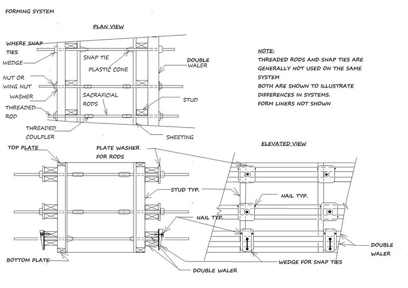
There are several different types of form ties that can be used. The standard systems used on bridges usually include threaded rods with she-bolts (threaded couplers) or coil rods and snap ties.
Snap ties can be ordered in specific lengths that account for the thickness of the plywood liners, stud dimensions and waler dimensions. It is common for snap ties to have a plastic cone that rests against the inside of the form liner. After the tie has been snapped the cone can be removed and a clean hole is left for patching.
When using threaded rod and she-blots or coil rods, the portion of the rod to be removed should have a release agent that allows them to be removed from the concrete.
There are advantages to either system. The snap ties leave a clean hole that is easy to patch, however they are typically not a strong and require tighter spacing. The threaded rod typically is a little more difficult to patch after removal but can be sized to maximize the spacing required.
The spacing is based on the rigidity of the system so that deflections are minimized during the pour and to assure the forms do not break when loaded. The standard specifications 706.03.D covers forming for standard pours.
There are times when premanufactured forming systems are used. The advantage to these is the ability to cast large, tall pours and to have pre-engineered form tie spacing. When using these systems, it is important to ensure all of the components and ties are in compliance with the manufacturer’s recommendations and calculations.
Steel Bands
Steel bands may sometimes be used to hold forms in place. These may eliminate or supplement the use of tie rods and bracing by encompassing the forms. The metal bands are drawn tight, crimped, and locked with a tool designed for this purpose. All bands should be checked for any rips and/or damaging folds. When using metal bands, temporary spreaders, struts and/or kickers will be needed to keep the forms from collapsing prior to concrete placement. The spreaders must be sized to maintain the design dimensions of form work. Wood spacers and any spacer other than appropriate chairs must be removed as the pour progresses and cannot be left as part of the pour unless approved by the engineer.
Walers
All walers need to be inspected, especially in corner areas, for loose or "floating" wale ends. Joints in a waler row may be strengthened by having the ends of the top and bottom members staggered with the butt ends in different tie rod spacings. All butt splices in walers must be scabbed. Forms erected and left in an erected position for even short periods, must be reinspected, keeping in mind that wind and weather can cause distortions of both forms and bracing.
Ties and hangers for walers must be fastened so that at lateral movements in the formwork will not disengage them from the walers. Wedges pins and other forms of attachment may be needed to stabilize the walers and hold them in place. Where the walers and studs or joists cross, a positive connection such as toe nailing should be used so that the members support each other laterally and do not spread or rotate during the concrete pour.
Stiffening longer braces is sometimes necessary. This may be done by spiking two pieces of lumber together into a tee-section or fastening a cross-member to a series of braces.
Many projects will incorporate steel or composite form materials. Often these are from a pre-engineered system. Typically, the studs are shop welded to the form surface or “skin”. The walers are typically steel angles or channels that allow positive attachment to the studs and form ties. The systems should be accompanied with installation direction and loading guidance provided by the manufacturer.
Inspecting Forms
Forms should be inspected when they show up on the site. The Contractor should be informed if reworking, relining, or replacement is necessary to provide concrete shapes and surfaces as specified. Seams in forms must be tight to prevent leaking. Overhead forms shall be sealed along all edges and seeps to prevent the loss of concrete and moisture. When over pedestrians, traffic, or other construction operations this becomes increasingly important. The plans are the usual source of information for steel reinforcement details about bar sizes, spacing, lap, etc. In forming the substructure units, it may be advantageous to weld an inner form rod to the end of a straight bar to continue with a form tie. Welding to the reinforcement is not acceptable and therefore when welding to a bar, it must be an additional bar added to the required reinforcement. An authorization is required for such welding.
Forming Footings
The Contractor will be furnished with a stakeout diagram and elevation references to use in determining footing locations and excavation or fill elevations.
Upon completion of the excavation or dewatering of the cofferdam, verify line and grade. A foundation soils check should be made by the Region Soils Engineer. Make sure that all necessary corrections indicated in the foundation inspection report are made before the forming is started.
On Design-Build projects, it is the responsibility of the contractor’s Geotechnical Engineer to determine if subgrade undercutting is necessary. The region Soils Engineer or representative must be notified and be present.
After the footing forms are in place, check for dimensions, elevations, alignment, and bracing. Notify the Contractor and Engineer of any discrepancies. All foreign material such as water, mud, sand, etc., must be removed from inside the forms because it will contaminate the concrete and/or effect the bond to reinforcement.
Forming Walls and Columns
When forming walls and columns, it must be remembered that great pressures develop with increasing height. The pattern of waler spacing may be closer together near the bottom and further apart approaching the top. During pouring operations when a tie rod ruptures, it will often "pop" with an audible crack (heard and not seen). The walers and tie rods should be checked immediately. Wind may also exert great force on large area wall forms and should be taken into consideration when bracing. When tall pours are cast, it is important to understand loading of the forms and the maximum pour rate in feet of pour height per hour. Review of the form shop drawings and or maximum loading is important. These things should formally be discussed with the contractor at the pre-pour meeting, progress meeting and again in the field at the time of pour.
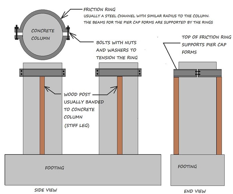
When round steel column forms are used, they should be inspected for out-of-roundness that results from rough handling such as rolling assembled sections off trucks, etc. The resulting egg-shaped column will make it difficult to properly fasten the friction rings used to hold the girder or cap. If there is any doubt about the friction rings supporting girder bottoms, Contractors should use timber or steel stiff legs, placed between rings and footing.
When casting battered walls (walls with one or more sloped faces), it is important to remember that the fluid mass of the concrete will cause the formwork to float. Substantial tiedowns may be needed to resist the buoyant forces on the wall forms. The contractor may attach form ties to driven piles, use a deadman system (weights or ballast) with ties or other methods to secure formwork.
With all wall and column formwork the structural steel reinforcement to formwork spacing needs to be verified at the bottom of forms prior to placing forms. This allows for adjustment of the forms if needed and eliminates the need to crawl into the formwork, which is a confined space. Bar chairs, spacers or additional ties may be needed to maintain bar to form spacing during the pour.
Partial metal bulkhead, joints and the small neoprene skirts used on the outside edge, which are fastened to the metal bulkhead within the wall, should be carefully and securely clamped between the vertical cant strips when moldings are called for. The stay in place meatal joint should be hot dip galvanized unless otherwise noted or approved by the engineer. The contractor may field fabricate the bulkheads which can be notched and placed in pieces to accommodate reinforcement through the joint. When placed in pieces it is important to make a positive connection capable of keeping the bulkhead parts properly aligned.
Floor Joist and Hanger
The size and spacing of joists and hangers used to support floor forms and their spacing are not given in the standard specifications since this depends on the form lumber thickness and the span distance between beams. These items should be proportioned to suit these conditions and design criteria. As per the Standard Specifications for Construction, the forms shall be designed to resist deformation or deflection more than ¼” or 1/180 of the form span length. 706.03.4.b
The wood floor joists should be properly proportioned and spaced to support the flooring without excessive deflection under the load imposed as per 706.03. Joists may be supported by metal hangers hung over the beams or on wood bracing resting on the bottom flanges. Metal hangers should be the proper length so the underside of the concrete deck haunches will be flush with the bottom of the top flange of steel beams and the top of prestressed concrete beams.
Permanent Metal Deck Forms
Some projects do not allow SIP forms. Before allowing the Contractor to place SIP forms verify that there is not a plan note or special provision dictating that SIP forms are not allowed.
Working drawings and design calculations for falsework will be submitted for approval by the contractor in accordance with subsection 104.02. The size and configuration of corrugated metal deck pans, straps, angles, and fasteners are available in the submitted documents.
Permanent Metal Deck Forms (Stay in Place Forms) need to be checked for size, material and quality before they are erected. The width, depth and configuration of the corrugations needs to be verified. All stay in place steel formwork must be galvanized according to Standard Specifications. When forming decks with stay in place formwork the size configuration of the supporting angles and strapping must be reviewed. The thickness, width and spacing of the straps is critical for the rigidity of the system. Angles must be sized and oriented so that the leg of the angle is down. When the haunch is equal to or less than the height of the corrugated deck pans, the vertical leg of the angle needs to be oriented upward. When the angle must be oriented with the vertical angle up, the angle must not extend above top of the metal deck pans. It is critical to keep the upwards angle as low as reasonably possible and below the standard bottom of deck elevation to prevent longitudinal cracking and eliminate interference with the bottom mat of reinforcement. Control of angles extending into the bottom of the deck often requires the contractor to have multiple sized angles. These sizes can be figured based on the deck pan thickness and the measured haunch grades. When placing deck forms it is common to have the haunches on one side of the beam higher than the other. This is most noticeable on bridges with a steep superelevation and wide beams.
Contractors will commonly add tabs to a concrete beam top flange during fabrication to allow welding of the support angles. If these are not present transverse straps or clamps must be placed to attach the angles. Welding to the sheer developers / stirrups for placement formwork is prohibited.
For structures with steel beams or diaphragms, the angles or straps must not be welded to structural steel.
For steel beam structures, it is important to weld only to the straps that are placed across the top of the beam to hold the angles. These straps should be oversized to accommodate the required length of weld while eliminating the possibility of arcing top the beams. If the welding, for any reason has arced to the top of the beam, the weld must be removed, the beam top ground smooth, and proper testing conducted in accordance with the Bureau of Bridges and Structures. Welding to the sheer developers / “studs” is prohibited for the placement of formwork. Additional studs may be added, in locations where studs are present, for the screed rail and or the expansion joint devices. Welding may be done on the additional studs.
When using stay in place forms, removable forms are required at expansion joints. This allows for future maintenance and or removal and replacement of the joint.
At longitudinal or transverse bulkhead joints ¼” weep holes are to be drilled in the stay in place forms at twelve inch maximum spacing.
The corrugations in stay in place forms need to be filled with a Styrofoam insert. Contractors no longer have the option to eliminate the inserts. Styrofoam inserts are placed to minimize the amount of non-reinforced concrete on the bottom of the deck and to minimize structural loading to the bridge. If adhesive is used, it needs to be verified to be compatible with polystyrene. If there are loose or fractured Styrofoam inserts, it is important to remove the loose pieces and replace.
Fascia Forms
Care should be used in supporting and bracing fascia forms to ensure a pleasing appearance of the finished line and grade. Most Contractors now use a manufactured fascia bracket.
This bracket or “Jack” consists of two legs braced with a diagonal member is fastened to the top flange by a threaded bolt and is braced against the bottom flange and the vertical leg can be adjusted vertically to obtain the proper grade.
Facia forms typically consist of an adjustable steel facia jack with wailers, joists, and plywood decking.
The jacks usually have steel angles hinged near the top and an adjustable strut that is used to adjust the slope of the decking. The vertical leg can be adjusted vertically to obtain the proper grade. Hard wood wedges are used to adjust the bottom of the deck and level the top of the facia jacks. Only hard wood wedges are acceptable. When placing facia jacks on a steel beam bridge, carpet or other padding must be placed on the jacks where they rest against the steel to minimize the potential to damage the paint system on the beams.
The jacks must be spaced as to eliminate excess deflection during deck placement. Because of the way jacks hang and the elevations required for the deck, walers and studs are often placed lying flat instead of standing on edge. The rigidity of this system is the responsibility of the contractor.
Because of their location in the finished bridge, barrier, curb and railing lines are most important for appearance. Forms for this work should be constructed, aligned, and braced with extreme care so they will remain rigid and true during the concrete placing. They should be graded for elevation, not just measured up a uniform distance from the deck surface or flange of beam. Forms scarred or worn from previous usage should be rejected before they are erected and braced.
When reviewing and setting the facia forms, they must be adjusted to meet the facia grades. The bottom of deck at the facia should be at or below the bottom of the top flange on the fascia side (see plan details for more information). This can be difficult to achieve when placing a new deck on existing beams. Ideally the top of the facia grade should follow the top of deck grade and the facia should be a consistent thickness. The grade is critical to provide a smooth uniform facia and provide even support for the barrier and barrier forming. The bottom of deck grades on facias occasionally require adjustment to meet thickness, reinforcement cover, and shape. If adjustments are needed, an even facia thickness is important to provide an aesthetic facia. The reinforcement steel on the bottom of the deck at the facia should have no less than 1 ½” cover and no more than 4” of cover. It may be necessary to place different bar chairs on the facias than in the normal deck section. When placing new decks on existing beams and when grade corrections are being made in the haunches, proper cover may be difficult to achieve. In these cases, contact BoBS and the Engineer of Record for guidance.
Use a ¾” cant strip to form a drip line between the facia and beams as located in the plans.
Part of the facia formwork is a vertical form. This usually consists of a ¾” plywood sheet and 2X4 studs with 2X4 top and bottom plates. Often the top plate is doubled.
If a Special Provision to move the screed rails for the finishing machine and/or work bridge to the fascia forms is included in the project the following applies.
- The Contractor must submit a PE stamped set of working drawings. The submittal must be reviewed and approved by the Engineer of Record and BoBS Construction Section. The approved version of the working drawings must be adhered to along with the special provision.
- Supporting the screed rail will typically require the facia forms to utilize a double 2X6 top plate with 2X6 studs and a 2X6 bottom plate.
- Remember to obtain good lines and grades in finished concrete. The forms must remain securely in place during concrete forming and be smooth and free of defect.
Steel Reinforcement
Epoxy Coated Reinforcement
Epoxy coated reinforcing steel must be stored on blocking or other padded surfaces and covered with non-transparent sheeting to prevent exposure to UV light. Reinforcement must also be protected from mud, water, contamination, nicks, and damage. The blocking must be arranged so the bars are off the ground for their entire length.
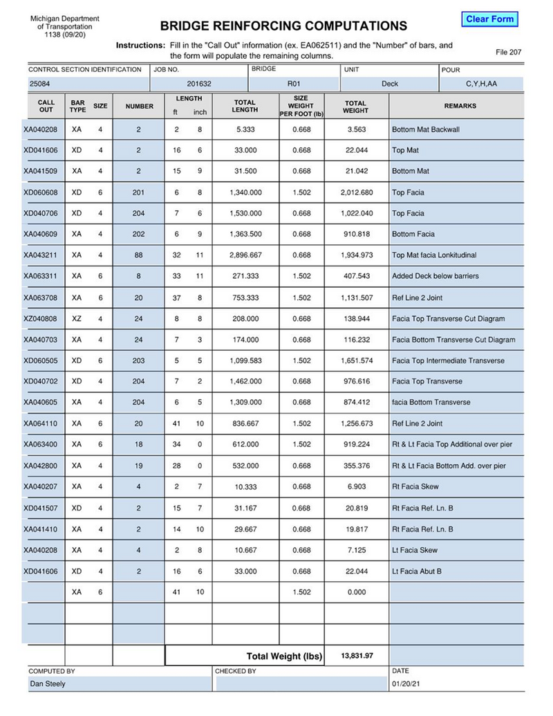
All reinforcing steel is to be reviewed in the plans and confirmed on Form 1138 (example below).
The 1138 includes each reinforcing steel bar call out which states the bar material, shape, diameter, length, number of bars required, weight per lineal foot, total weight and location of the bars. This is to be submitted with the Inspector’s Daily Report.
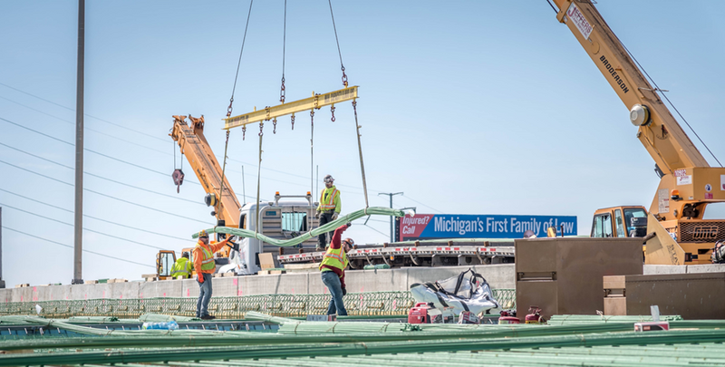
Lift reinforcing steel with padded contact points, using multiple contact points and a spreader device. Care must be taken to prevent abrasion of the epoxy coating during transportation of reinforcing steel. Do not allow the reinforcing steel to be dragged across the ground, forms, or other reinforcing steel.
Damaged epoxy must be touched up with an approved two-part epoxy prior to casting concrete.
Do not allow the Contractor’s employees to clean concrete placement tools by banging them on the epoxy coated reinforcement.
Placing and Fastening
Each layer of reinforcing steel in the superstructure must be supported over the forms by approved chairs. Bar chairs are placed parallel to the beam and spaced (as measured between beam centers) at approximately the 1/4 and 3/4 points for beam spacings less than 9 feet and at approximately the 1/6, 1/2 and 5/6 points for beam spacings 9 feet and over.
Some decks are now being designed with the empirical method and the top mat may flip the order of transverse and longitudinal reinforcement. Check the details in the plans before setting the mats. If the empirical method is used, extra bar chairs will be needed to keep the top mat stable. The Department does not pay for the extra chairs.
Additional bar chairs are required outside the fascia beam to support the reinforcing steel along and near the fascia. On concrete box beams without slab ties, a bar chair will be required along the longitudinal centerline of each beam. Chairs used at the fascia are typically different sizes than the ones needed at interior locations.
The upper layer of reinforcing steel will be supported over the supports for the lower layer of steel with rows of approved continuous steel bar supports consisting of a minimum of three longitudinal wires. Supports for holding reinforcement will be approved plastic or coated metal chairs. Bar chairs for the top mat of steel are to be placed directly over the bar chairs below the bottom mat of reinforcement. When there are wide beams and relatively narrow bay making the ¼ and ¾ points impractical for the bottom row of bar chairs, place the bottom row as close to the edge of the beam as the deck forms will allow and place the top mat directly above them. If beams are wider than 4’ or there are smaller than #5 transverse bars, an additional row of chairs may be needed above the beam line for stability.
The stability of the mat is important to maintain the bond of the plastic concrete and the rebar intact during concrete placement which requires workers standing on the reinforcement. Occasionally an additional row of bar chairs will be placed near the centerline of the beam between the top and bottom matts of reinforcement. This has proven to provide additional support with wider beam.
When placing the top and bottom mat reinforcing, a check should be made on the bar size, number, spacing, length, tying and test tags. The bottom mat of reinforcement must be tied at a minimum at alternate intersections where spacing is such that the product of the length and width is less than 120 square inches. Where the spacing is greater, all intersections must be tied. The top mat must be tied at all intersections regardless of spacing. This includes additional bars on the bottom of the top mat over piers, in sharp skew angles and any other reinforcement steel tied to the top mat.
All bar lap splices must meet the minimum length in the plans, and be tied within 3 inches of each end of the lap. All ties must be done with coated wire.
Bars must be placed in the mat so the variation in spacing between adjacent bars does not exceed 1/6 of the spacing shown on the plans, and clear cover must comply with what is shown in the plans. Check cover for the ends of bars at forms and joints as well.
The top mat of reinforcing steel must be securely tied to the structural member at 5-foot intervals along each beam or girder.
No bar substitutions are allowed without written approval from the Engineer of Record.
Welding steel reinforcement is prohibited.
Additional notes for Substructure Reinforcement Placement
- Any mat where the product of the length and width of spacing is less than 120 square inches may be tied at alternate intersections. If the product is larger than 120 square inches every intersection must be tied.
- The bottom mat of a footing may be supported by left-in-place commercial grade concrete brick while the top mat is suspended by tie wire that is cut off and tucked into the concrete before it has attained its initial set. The top mat may be supported by adding K-bars. If K-bars are added to support the top mat, associated cost will be the responsibility of the contractor.
Additional notes for Footing Reinforcement Placement
- If a template is used to hold vertical steel in place during concrete placement, it should be laid out by the Contractor and verified by an inspector prior to the pour.
- All vertical reinforcement must be installed and tied in place prior to placing concrete. Do not allow the Contractor to “stick” vertical reinforcement into the plastic concrete during placement as it does not allow the concrete to properly consolidate around the reinforcement.
Placing Galvanized Metal Pipe Sleeves
-RESERVED-
Placing Conduit
-RESERVED-
Placing Concrete
Subfooting Concrete
The purpose of a subfooting is to provide a working surface on which footing forms may be erected, reinforcing steel placed and substructure concrete cast without the presence of mud or water. Typically, subfootings have no structural significance and pegs may be inserted for bracing the bottom of footing forms.
Subfootings are not normally required in construction of structures. Exceptions will be indicated on the plans or recommended by the Region Soils Engineer. Subfooting will be paid as Concrete, Grade 3500.
Construct subfootings to the dimensions given in the plans. Edge forms are to be placed to assure that the proper line and grade are met. Line and grade need to be verified to assure the footing will be in the proper location. The subfooting is typically larger than the footing to allow room for substructure formwork.
When subfootings are required, foundation excavation will be measured to the bottom of the subfooting rather than to bottom of the footing. If the Contractor elects to place subfootings at company expense, payment for unclassified excavation will be measured to plan bottom of footing only. If subfootings are used, all inspection procedures will be followed as dictated under footings.
Footing and Substructure Concrete
Prior to placing footing concrete, verify that the piles are clean and properly cut off. If CIP piles are being used, verify that the area between the shell top and the top of the concrete core are also clean (generally the core is filled to within 1 inch of the shell top). Also verify the distance from the pile to the forms complies with the plans and specifications.
Make sure that the placing of the concrete does not dislodge reinforcement.
Concrete should be placed in a continuous operation with no interruption in excess of 45 minutes between the placing of contiguous portions of concrete. Consolidation should be by means of mechanical, high frequency internal vibrators. Vibrators should be manipulated to thoroughly work the concrete around the reinforcement and embedded fixtures, and into the corners and angles of the forms. The vibrators should be inserted vertically and withdrawn slowly. Concrete is to be placed in lifts no deeper than 36 inches thick and not allowed to freefall more than 5 feet. If concrete needs to be dropped more than 5 feet a pipe of more than 6-inch diameter or pump hose must be used to place the concrete.
Do not allow the Contractor to vibrate the concrete beyond what is necessary for consolidation as it will cause segregation and/or localized formation of grout. When concrete is over-vibrated air bubbles will be present and the paste will begin to come to the surface. When attempting to move concrete with the mechanical vibrator, over-vibration is likely. When epoxy coated steel is used protective covers must be used on vibrators.
Slump tests, air checks and temperature checks are required.
The top surface of the concrete will be finished with a wooden, magnesium, or aluminum float to a smooth and level surface. During the finishing operation, verify that a keyway conforming to approximate plan dimensions is placed where called for on the plans. Curing should be started as soon as possible after finishing. Do not allow the curing to be interrupted during the forming of subsequent pours.
New for the 2020 Standard Specifications is the requirement that reinforced substructure concrete elements must be cured for 3 days AND obtain 70% of the required strength before placing additional concrete on top. If the Contractor’s method for setting forms for subsequent pours involves heavy equipment, do not allow it to touch the substructure element.
Superstructure Concrete
Before placing any deck concrete, the inspector should check the forms and reinforcing steel to ensure cleanliness. All forms, joints and screeds should also be checked to ensure that their alignment and grade are correct. Check the details for the expansion device and verify the deck measurements to ensure the expansion device will fit properly after the deck is cast. Expansion joints are to be placed ¼” to 3/8” below the top surface of the deck.
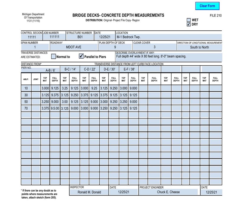
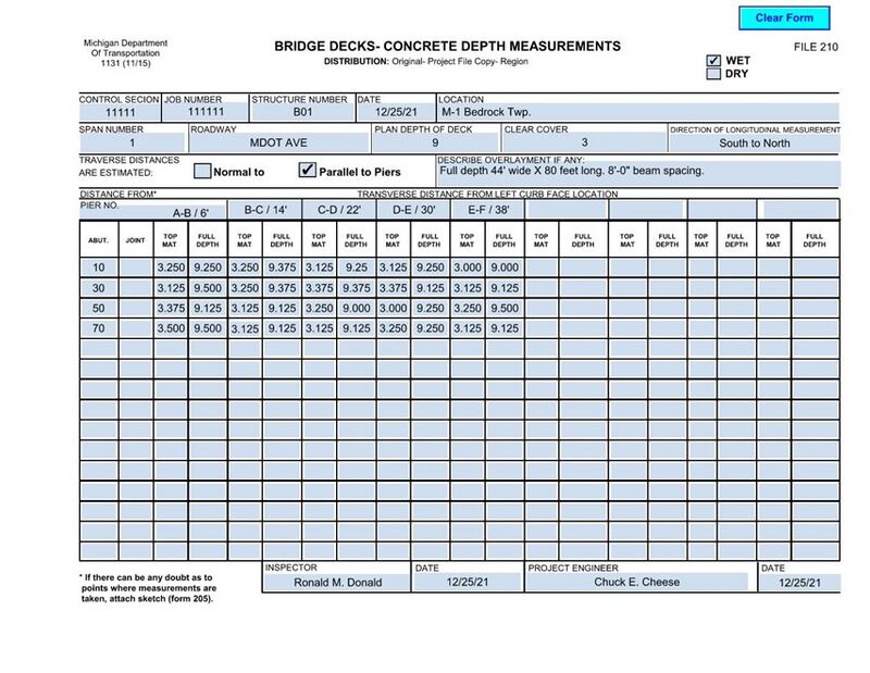
Setting the screeds on finishing machines is to be done by Contractor personnel from information shown on the plans or provided by the Engineer. Checking the screed is to be done by the inspector. After the screed rails have been set, the finishing machine is passed over the deck to check for plan slab thickness and reinforcement cover. Record results on Form 1131 “Bridge Decks – Concrete Depth Measurements” as dry measurements.
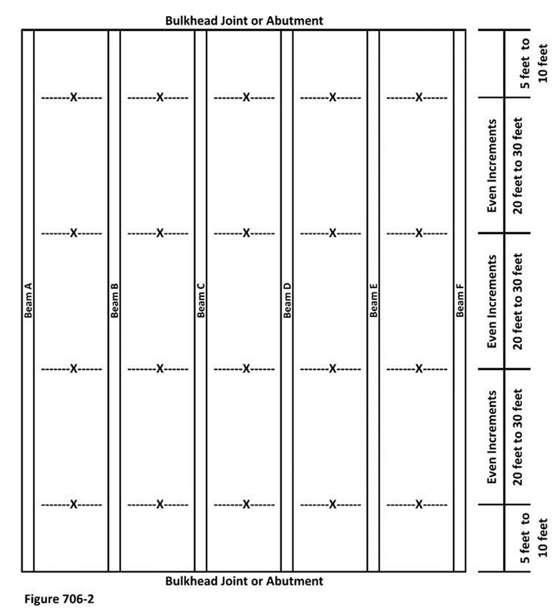
Dry run measurements should be taken between 5 feet and 10 feet from each bulkhead, then at some interval (ex. 20 feet) for the remaining distance, including center span (see example below). If distances are much less than 20 feet, it will be difficult to get all measurements and due to timing can become distracting and unsafe. If spacings are over 25 to 30 feet, there may not be adequate checks to make sure the deck and finishing machine are reacting as planned. Transverse spacing should aim for the center of each bay. When casting the second half of part width decks, or if paving decks where widenings or beam lines are added, it is critical to contact BoBS Bridge Construction for screed set up. It is best to involve BoBS prior to setting deck forms due to the complexity of operations.
Wet measurements must be taken during the concrete placement, and at or near the same locations as the dry run measurements. Record results on Form 1131 “Bridge Decks – Concrete Depth Measurements” as wet measurements. Enough wet checks should be taken at each location to ensure that proper cover and thickness is being obtained. If depth checks show a lack of cover or thickness, additional checks should be taken.
When there are many narrow bays, it is still recommended to perform dry and wet measurements for all bays. Work with the operator of the finishing machine to pause the carriage of the paver so that the depth checks can be safely measured.
When casting the second half of part width decks or if paving decks where widenings or beam lines are added, a tighter frequency of depth checks may be needed. The additional checks are needed to adjust loading the deck for beam deflection differences. In these cases where the screed rail is on a member that does not deflect with or at the same rate as the remainder of the beams, the deck may need to be preloaded to deflect beams and ensure proper thickness and ride quality. Typical pour rates vary from forty to eighty cubic yards per hour. If this is the case, contact BoBS Bridge Construction for allowable lead time between placing and finishing the concrete.
Depth Checks are to be taken as close to the center of each bay as possible. Normally flagging is tied to the frame of the screed at the time of the dry run. The flagging is placed to assure that you can do both dry and wet measurements as close to the same location as reasonably possible.
If a pour is less than 40 feet in length, measure only the two rows 5 feet to 10 feet from the bulk heads or reference lines.
If the length of the pour is between 40 feet and 60 feet, take the measurements at the two rows 5 feet to 10 feet from the bulkheads and one near the center of the bridge.
If the pour length is over 60 feet, measure at 5 feet to 10 feet from both bulkheads and divide the remainder into sections between 20 to 30 feet.
Do not allow the Contractor’s employees to clean concrete placement tools by banging them on the epoxy coated reinforcement.
Nighttime Casting of Superstructure Concrete
-RESERVED-
Cold Weather Precautions
-RESERVED-
Construction and Expansion Joints
Make sure that forming for joints is well secured before casting as any movement of the forms will create a major problem with joint alignment. Be sure that expansion is provided in the forms when casting across an expansion joint.
Joints in Substructure Elements
Joints are a source of considerable trouble. The Contractor cannot be too careful when placing joints. Joints must be kept straight and true at all times, particularly when premolded neoprene joint sealer is to be used. Make sure that forming for the joints is well secured before pouring substructure concrete.
Verify that the alternative partial metal bulkheads are allowed in the plans prior to the Contractor installing them.
Fiber Joint Fillers
Where joint filler is used, it is to be placed and adequately supported prior to starting the concrete pour. The material must be tested prior to use. It is best used in as large a piece as possible to avoid numerous concrete fins in the joint. During the concrete placing, precautions are necessary to avoid damaging or displacing the material. It is important to cut the fiber joint filler carefully and fill all holes so that plastic concrete does not cause a stress point within the joint. Often the holes are filled with polyurethane foam. Where fiber joint filler is used it is not intended to be exposed to the elements. Typically, a silicone caulk will be used to seal edges of the fiber paper. The sealant assures that concrete and slurry do not flow around the joint filler with an incompressible material. It also protects the joint filler from ultraviolet light.
On vertical surfaces where there is no support under the joint, the material should be firmly attached to one of the contacting surfaces to prevent it from falling out, when the concrete contracts and the joint opens. It is normal to place a ¾ inch cant strip along the edges of the fiber joint filler. Special care must be taken when machine-finishing decks to keep the filler in position due to the lack of support in the absence of conventional joint forming. This is usually accomplished by evenly placing and consolidating concrete on each side of the joint. Placing the fiber joint filler all the way to the form will help prevent it from moving during the pour. Excess material can be cut out once the concrete has hardened and the forms are removed.
Polyurethane Joint Sealant
Polyurethane and polyurethane hybrids are becoming the most common sealant for joints on structures. When the plans call for their use make sure that the Contractor is following FUSP 12SP-706C. When placed on traveled surfaces, the sealant needs to be kept below the surface of the concrete to prevent tracking.
Expansion Joint Devices
The current standard joint set is at a two-inch opening, unless otherwise shown on the plans. Most standard expansion joint devices allow for four inches of movement. If the joint device is set at two inches, it will allow for two inches of contraction and two inches of expansion. In the case where the plan expansion or contraction will exceed one inch the designer and BoBS should be contacted for guidance. In those cases, the joint should be set based on temperature or a different joint device may be needed.
Expansion joint devices are to be placed ¼” to 3/8” below the top surface of the deck, and in accordance with the contract.
Verify that the Contractor uses an approved expansion joint device and document the type used.
If the joint device does not arrive in a single piece, all welding must be done in accordance with 707.03.E.7.b, d, and f. Make sure that the gland area is protected during all welding.
No welding to structural members, including diaphragms, is allowed to support the expansion device. Supports may be welded to shear studs or form hanger supports. Clamping devices are permitted.
All damaged galvanized surfaces must be repaired in accordance with 716.03.E.
Concrete beams may have inserts or steel tabs cast into the beam to allow for additional welding locations. Where additional shear studs and welding tabs is not practical, additional clamping devices may be used.
Shipping bolts need to be cut or removed prior to casting the deck. This requires additional supports on either side of the joint. When the shipping bolts are not cut prior to casting, beam movement loosens the dowel rods or studs that hold the joint into the deck. The loosened attachments will allow the joint to move and eventually fail. Failure of the joint can also be caused by paving away from the joint.
When casting decks, it is common to use two-inch-thick polystyrene in the joint device. Concrete will need to be placed and vibrated evenly on both sides of the joint to prevent movement or breaking of the polystyrene sheets. When the joint is the bulkhead beginning or ending the pour, additional bracing and or plywood forming will be needed to hold the polystyrene in place.
Sleeper Slabs with Expansion Joints
New designs may incorporate sleeper slabs and structural approaches to keep expansion off the bridge. This method of allowing the bridge to expand and contract outside of the limits of the bridge, prevents damage to the structure if an expansion joint fails or leaks. The sleeper slab design uses a large T shaped concrete foundation (sleeper) to carry both the road approach and the structural approach to the bridge. The large T shaped sleeper prevents settlement of the approach at this location. The structural approach is reinforced similarly to a bridge deck and is designed to carry the design load in the event the structural back fill below is washed out.
Below the structural approach and sleeper slab, open-graded drainage course (OGDC), or aggregate base compacted at 98% should be used to facilitate drainage and prevent loss of material. This type of sub grade in conjunction with the concrete sleeper will prevent settlement and provide a smooth transition from the road to the bridge. There should be two layers of 0.015” (15 mils) polyethylene sheeting on top of the aggregate base, or OGDC, to act as a bond breaker.
The expansion joint rail is installed at the joint between the sleeper slab and the structural approach.
Sleeper slabs are to be placed and cured in the same manner as the bridge deck.
To provide a more consistent ride some Contractors will propose pouring the stem of the sleeper T with the approach. Consult with BoBS before allowing.
Placing Anchor Bolts and Position Dowels in Concrete
-Reserved-
Finishing Plastic Concrete
Machine Finishing
The second paragraph of subsection 706.03.M.1 describes the requirement for the Contractor to perform a “dry run” check. A dry run is critical to making sure that everything is properly set for the actual pour and needs to be witnessed by QA staff. Dry runs are also important for setting up wet check location markers. Notify the BoBS Construction Group of any dry run. See the Superstructure Concrete Placement section for more information.
Curing
Proper concrete curing is critical to durable concrete. It is based on the idea of retaining the mixing water in the concrete as hydration takes place. This is achieved by either sealing the surface and retaining the mix water, or wet curing to prevent evaporation.
For most concrete, curing should be started as soon the sheen begins to dissipate from the concrete surface after the concrete is placed and finished.
Subsection 706.03.N should be reviewed for specific curing requirements. Bridge decks and top surfaces to which succeeding portions will be bonded require a 7-day wet cure. All other surfaces must be cured for five days.
Do not allow the Contractor to interrupt the 7-day wet cure for any reason.
Substructure units can be left in the formwork to provide protection from evaporation. The forms if left in place for cure shall not be loosened and left in place for a minimum of 5 days and 70% of its’s specified 28-day compressive strength. If left in forms all exposed surfaces need to be cured with membrane cure.
When wetted burlap or other similar curing types requiring water are used, they should be checked frequently to ensure that the concrete surface is kept continuously wet. This is especially true on hot, dry, and breezy days.
Bridge Deck Curing
Prior to placing deck concrete verify that the Contractor has all curing material on hand and prepped, and make sure that all equipment is functioning properly.
Bridge decks require a two-phase wet curing system and should be started as soon as texturing is complete. The first phase is an application of white curing compound. Care should be taken to prevent overspray in sidewalk, parapet, brush block, barrier, etc., areas as this spray has been found to destroy the bond of subsequent concrete pours. If curing compound contaminates these areas, it needs to be fully removed prior to the subsequent pours.
When reinforcement for subsequent pours is in place, it must be protected from spray cure or thoroughly cleaned prior to casting subsequent pours. The cure will act as a bond breaker between the steel reinforcement and the concrete and therefore must be removed prior to pours. Do not blast clean epoxy coated reinforcement. Where cure compound has been applied over epoxy coated reinforcement power washing, steam cleaning and or solvent cleaning may be necessary to completely remove the cure.
The second phase includes pre-soaked burlap, soaker hoses, and polyethylene sheeting. While the first phase is to be applied immediately following texturing, the second phase needs to wait for the curing compound has dried and the concrete can support the burlap without deformation. Do not let the Contractor wait until they can walk on the deck as this is too late.
The burlap is required to be soaked for at 12 hours prior to use but needs to be hung up to drain excess water prior to placing it on the deck.
When lower temperature placement occurs or when slag cement is used in the mix, concrete may not attain enough strength to place wet cure for several hours. When this occurs, it is important to regularly monitor the concrete so that the wet cure can be placed as soon as possible.
When placing Silica Fume Modified Concrete SFMC, the curing must begin immediately. Due to the water demand for SFMC mixes wet curing needs to be staged before the surface dries and the sheen disappears from the concrete. On SFMC deck overlays the work bridge needs to closely follow the screed, Continuous fogging is required, and the burlap, soaker hoses, and polyethylene sheeting placed from the work bridge directly behind the tining.
Removing Falsework and Temporary Supports
-RESERVED-
Removing Forms
-RESERVED-
Placing Beams on Substructure Units
-RESERVED-
Finishing Hardened Concrete
-RESERVED-
Penetrating Water-Repellent Treatment
This treatment is commonly used on piers and abutments beneath deck expansion joints to shield bearing areas from corrosive elements. There are two general types of water repellant treatments, penetrating water repellants and horizontal surface sealer. The standard specifications address the penetrating repellents. The horizontal surface sealer is an epoxy coating and is addressed in FUSP 20SP-710C. The concrete substrate must be clean, dry, and free of oil, grease, latencies, cure compounds and other foreign materials that will prevent proper application, and at least 28 days old. Additionally, the horizontal surface sealer preparation includes light abrasive cleaning of the surface, followed by oil free compressed air cleaning. Wire brushing or high-pressure water blasting are not allowed for horizontal surface sealers.
Electrical Grounding System
-RESERVED-
Name Plates
-RESERVED-
Wall Drain
-RESERVED-
INSPECTION & TESTING
-RESERVED-
MEASUREMENT, DOCMENTATION & PAYMENT
-RESERVED-
