718 - Drilled Shafts
GENERAL
Drilled shaft foundations are also referred to caissons, drilled piers, or bored piles, and consist of circular shafts of varying diameter, drilled to a design depth, reinforced with a steel rebar cage, and filled with concrete. Drilled shaft foundations can support large loads, and are used when driving steel piles is not feasible, or surrounding structures or utilities are too sensitive to survive the vibrations from steel foundation pile driving operations. Like steel foundation piles, loads from the superstructure transfer into the drilled shafts, which transfer loads to soil layers through side friction, end bearing, or a combination of the two. Drilled shafts are used for bridge foundations, and other ancillary structure foundations such as sign cantilevers and trusses, and signal strain poles.
Drilled shafts can be constructed in the dry, or in the wet, and can also include a steel casing.
DRY CONSTRUCTION METHOD
Dry construction methods are generally used when the water table is below the bottom of the shaft, and the existing soils are stiff enough as not to sloughing or caving into the hole during drilling operations. Any accumulated water greater than 3 inches at the bottom of the shaft must be pumped out prior to rebar and concrete placement, and during concrete placement, water cannot flow into the shaft at a rate greater than 12 inches within 1 hour.
Typical issues with dry construction methods are if the soils are unstable, or the water table is too high, but the Contractor attempts to force dry shaft construction. In this scenario, soil caving problems will lead to soil inclusions in the shaft concrete, affecting the shaft integrity. If any problems like this arise during construction, contact the Geotechnical Services area.
Another issue to watch for is if the Contractor leaves the excavation open for too long prior to reinforcement cage and concrete placement. Soils that were capable of maintaining hole stability during the drilling operations may shrink or swell over time and slowly lose that ability, resulting in caving leading to soil inclusions in the shaft concrete affecting the shaft integrity.
WET CONSTRUCTION METHOD
Wets construction methods are generally used where a dry excavation cannot be maintained during drilling, or shaft concrete placement. This typically occurs in areas of high water tables, and sandy soils that would otherwise slough or cave into the shaft during drilling operations. Water or a polymer slurry is used to contain water seepage, and maintain stability of the shaft excavation. Polymer slurry must be de-sanded and cleaned if used. Temporary surface casings are typically used to ensure shaft alignment. The rebar cage is lowered into the shaft, and concrete is placed using a tremie tube, or concrete pump capable of reaching the bottom of the shaft.
Typical issues with wet construction methods are inexperienced Contractors that do not understand the mechanics of polymer slurry construction, and the need to ensure proper suspension of sediment and cuttings for removal, and control of caving. This can lead to shafts not being properly cleaned of sediment, resulting in voids, or inclusions in the concrete, affecting the shaft integrity.
DRY TEMPORARY CASING METHOD
Dry temporary cased construction methods are generally used where caving soils occur, over soil or rock deformations are expected, but the casing can maintain a dry and stable excavation. The casing is advanced simultaneously with the excavation. After placement of the rebar cage, the casing is then withdrawn slowly during concrete placement until removed at the top of shaft.
WET TEMPORARY CASING METHOD
Wet temporary cased construction methods are generally used where caving soils occur, and a dry excavation cannot be maintained, the soils are too permeable, and the groundwater is higher than the bottom of the shaft. The casing is advanced simultaneously with the excavation, but it is important that no drilling occur outside the casing through any caving soil layers. After placement of the rebar cage, the concrete is placed using a tremie tube or concrete pump capable of reaching the bottom of the shaft. The water in the casing is not to be pumped out, rather it is to be displaced by the concrete placement.
It is important to ensure the Contractor maintains a positive fluid pressure head in the shaft above the ground water elevation, or material from the side walls of the shaft will be pulled into the bottom of the shaft.
For both the wet and dry casing methods, the casing is typically installed in a telescoping fashion, where the top casings may be larger than the drilled shaft diameter as called for on the plans. The depth of the hole will also dictate how many sections of casing are to be used. Ensure the contractor does not telescope the casings down to a diameter less than the design diameter as shown on the plans.
MATERIALS
Concrete, Grade S2, and Grade T
Ensure concrete materials are in accordance with section 701 of the Standard Specifications for Construction, except modifications for the slump requirements per subsection 718.02 of the Standard Specifications for Construction. Concrete Grade S2 is to be used for dry construction, and Concrete Grade T is to be used for wet construction.
Concrete mix design and spacing of reinforcing bars are critically important construction parameters that help ensure the free passage of concrete through the cage and into the space between the cage and borehole wall.
The modified slump requirements described in subsection 718.02 of the Standard Specifications for Construction supersede the slump requirements shown in Table 701-1A in Section 701 of the Standard Specifications for Construction. Construction staff must review and only approve contractor submitted concrete mix designs and concrete quality control (QC) plans, for drilled shaft construction, that meet the modified slump requirements of subsection 718.02 of the Standard Specifications for Construction. The Special Provision for Quality Control and Acceptance of Portland Cement Concrete, 12SP-604B-05, does not supersede these requirements.
If concrete for drilled shaft foundations does not meet the modified slump requirements of subsection 718.02 of the Standard Specifications for Construction it should not be allowed.
Steel Reinforcement
Ensure steel reinforcement bars are in accordance with section 905 of the Standard Specifications for Construction. Check the plans and specifications for epoxy rebar requirements.
Steel Casing
Ensure steel casing materials are in accordance with section 919.10 of the Standard Specifications for Construction. Permanent casing will also require Buy America certification, temporary casings will not, unless left in place.
Review the plans for temporary casing-left in place cut off elevations. The Contractor is required to provide casing to be smooth and watertight, and capable of withstanding the pressure of concrete and the lateral earth pressures exerted down the length of the shaft. Ensure the outside diameter of the casing is at least equal to the diameter of the shaft as called for on the plans.
Temporary casings should come equipped with hook holes, or other attachments to aid in the removal as the concrete pour advances. The concrete placement is to be complete prior to complete removal of the casing. The casings should be removed slowly, and with pull forces being in line with the shaft axis. Do not allow the contractor to pull shaft casings with equipment offset from the centerline of the shaft, as this will either disrupt the already placed concrete, or case caving of soil materials into the plastic concrete.
Polymer slurry
When wet construction methods are required, polymer type slurry is required. Bentonite slurry is prohibited. Ensure the polymer slurry is of sufficient specific gravity to ensure stability of the excavation during drilling operations, and allows for concrete placement. The Geotechnical Services area will typically review and approve the Contractor’s proposed polymer slurry materials.
Ensure any polymer slurry used meets the requirements of Table 718-1 from the Standard Specifications for Construction. Ensure the Contractor maintains the height of polymer slurry to prevent the side walls of the excavation from caving, and the bottom from heaving.
Ensure the contractor pre-mixes the polymer slurry materials with clean, fresh water, and allow time for hydration prior to pumping into shaft excavation. The polymer slurry should be agitated to prevent setting up in the shaft.
If de-sanding is required, ensure the Contractor provides the appropriate equipment. Prior to placement of shaft concrete, take polymer slurry samples with a polymer slurry test kit to determine if heavily contaminated polymer slurry at the bottom of the shaft is to be removed. Ensure the Contractor controls and collects polymer slurry exiting the excavation as the concrete displaces the volume. Review the plans for polymer slurry handling and disposal requirements.
CONSTRUCTION
Equipment
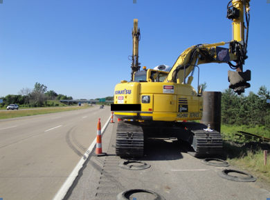
Ensure the contractor is using appropriate equipment to drill the shafts given the site conditions reported in the soil borings, and geotechnical subsurface exploration report. See Figure 1 for a typical drill rig set up. The major components of drill rig include:
- Crawler or truck mounted auger
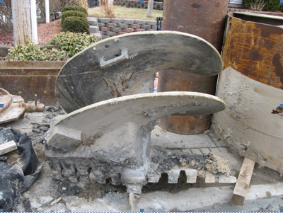
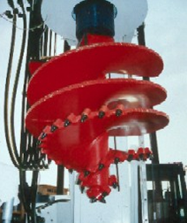
- Auger of the appropriate type – rock auger, single or double flight earth auger. See Figure 2 for a double flight earth auger, see Figure 3 for a single flight rock auger.
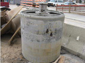
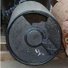
- Muck or clean out bucket – see Figures 4 and 5 for a muck bucket example.
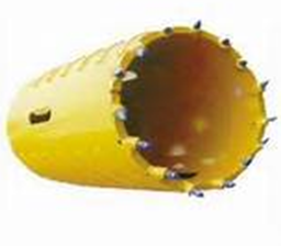
- Rock core barrel – see Figure 6 for a rock core barrel example.
DRILLED SHAFT CONSTRUCTION
To track drilled shaft operations, use MDOT form 1988 – DRILLED SHAFT INSPECTION RECORD FOR HIGHWAY SIGNS, LUMINAIRES, AND TRAFFIC SIGNALS.
Prior to Drilled Shaft Operations
The Contractor is required to submit a Drilled Shaft Installation plan, per subsection 718.03.A of the Standard Specifications for Construction. This plan is to detail all equipment to be used, the construction sequence, rebar and concrete placement, etc. The Geotechnical Services area will review and approve the Drilled Shaft Installation plan. Review and understand the following:
- Proposed equipment, including cranes, drills, augers, core barrels, bailing buckets, cleaning equipment, polymer slurry pumps and cleaning equipment, tremie tubes or concrete pumps, and casing.
- Construction sequence, including methods to ensure a stable excavation, and removal of materials at the bottom of the shaft prior to rebar cage placement.
- Shaft excavation methods, including proposed excavation methods through supporting and caving soil layers.
- Method to mix, circulate and de-sand polymer slurry for wet construction methods.
- Reinforcement placement, including support and centering methods.
- Concrete placement, including free fall, tremie, or concrete pumping procedures.
- Methods to prevent drilled shaft excavation spoils from entering waterways, wetlands and floodplains.
- Fall protection plan conforming to MIOSHA Construction Safety Standards, including a rescue plan for shafts with a diameter of at least 30 inches, and at least 6 feet deep. This must be in place prior to commencement of any drilling operations.
- Conformance with shaft diameter and rebar requirements based on details shown in the plans.
Ensure the Contractor has brought all of the proposed equipment as stated in their approved Drilled Shaft Installation plan.
If the shaft is to be constructed during the wet method, verify if the Contractor is allowed to use water as the drilling fluid, or if polymer slurry is required. Typically, Contractors will want to use water, but water will not prevent caving in deeper shafts. The use of bentonite slurry is prohibited.
During Drilling Operations
Ensure the Contractor performs the following:
- Check the drilled shaft dimensions and the alignment with reference stakes and plumb bob.
- Check the dimensions and alignment of the casing inserted in the excavation.
- Insert a rigid rod assembly with several 90-degree offsets equal to the shaft diameter into the shaft excavation to ensure required diameter.
- Construction Method Log: The Contractor is required to submit a daily construction method log during drilled shaft excavation and construction per subsection 718.03.5 of the Standard Specifications for Construction. Ensure the following information is shown on the logs:
- Start dates and completions dates
- Drilled shaft identification number
- Location
- Actual top and bottom elevation of drilled shaft
- Shaft diameter
- Final centerline location at top of shaft
- Variation of drilled shaft from plumb
- Top and bottom elevation of any permanent casing
- Description of each soil and rock material encountered during excavating and the top and bottom depths or elevations
- Depth drilled into bearing stratum
- Top and bottom elevations of obstructions encountered
- Amount of obstruction time
- Depth or elevation of encountered seepage of groundwater
- Actual volume of concrete placed, compared to the theoretical concrete volume to detect any large void or intrusions of extraneous materials
- Any remarks to better describe operations.
Ensure the Contractor maintains the required drilling fluid or polymer slurry levels to prevent caving.
Construction tolerances – Ensure the drilled shafts are within 3 inches horizontally of centerlines shown on the plans, and the drilled shaft is no more than 1 percent out of plumb, as measured horizontally from the actual center of the shaft at the shaft design top elevation.
Ensure the Contractor cleans each shaft so at least 50% of the base contains less than ½ inch of sediment. The shaft bottom should have no more than 1 ½ inches of debris above the required bottom elevation. Use a weighted tape to check the bottom of the shaft excavation for debris.
Marks on the Kelly Bar should be checked to ensure the required bottom of shaft elevation. Monitor the excavation to ensure the expected amount of materials are removed by the auger, if not, caving soils are present.
Ensure the top elevation of the drilled shaft is from +1 inch to -3 inches from the top of the shaft elevation shown on the plans. For shafts outside of this tolerance range, contact the Geotechnical Services area for recommendations as to corrections. Subsection 718.03.C.4 of the Standard Specifications for Construction dictates contractual obligations of the contractor to correct out of tolerance shafts.
Verify the soil cuttings as they are removed from the auger, and notify the Geotechnical Services area if soil cuttings appear different than those shown on the soil borings. Ensure the Contractor stores soil cuttings away from the drill shaft locations.
Obstruction Removal
Obstructions are to be removed per subsection 718.03.F.2 of the Standard Specifications for Construction. Obstructions may include old concrete foundations, abandoned utilities, or boulders and cobbles. Ensure the Contractor uses tools and procedures as approved by the Geotechnical Services Section to remove the obstructions. Special procedures and tools include:
- Chisels
- Boulder breakers
- Core barrels
- Air tools
- Hand excavation
- Temporary casing
- Enlarging the drilled shaft diameter
Removal of obstructions that require special equipment or tools will be measured and paid for as extra work per subsection 718.04.D of the Standard Specifications or Construction. A budget amount will be established to pay for removing obstructions. If the Contractor and the Engineer cannot agree on a lump sum price, the Engineer will direct the work to be done on a force account basis.
Placing Steel Reinforcement
Check the plans and specifications to verify the Contractor is using the correct size longitudinal bars and lateral or spiral reinforcement, and correct bar lap lengths if used.
Reinforcing cage – maintain the top of the reinforcing steel cage no greater than 1 inch above, and no greater than 3 inches below the required position. Measure the distance between the top of shaft and the top of reinforcing cage with a straight edge, and direct the Contractor to correct the position if out of tolerance.
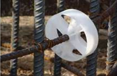
Ensure the Contractor provides a fully assembled steel reinforcement cage for inspection at least two working days before the start of construction. Ensure all longitudinal bars and lateral or spiral reinforcement is properly tied. Ensure plastic spacers are tied at the quarter points around the cage perimeter, but no greater than 30 inches apart.
Ensure the plastic spacers are spaced at intervals no greater than 5 feet along the length of the cage for #8 bar or smaller, and 10’ for bars larger than #8 to ensure a minimum annular space of 3 inches between the outside of the cage and the side of the excavation or casing. See Figure 7 for an example of plastic spacers on the rebar cage.
Ensure the Contractor does not use concrete blocks, wood blocks, or metal chairs as spacers, as these will not retain the required spacing, and will shift out of position during cage lowering, or during the concrete pour.
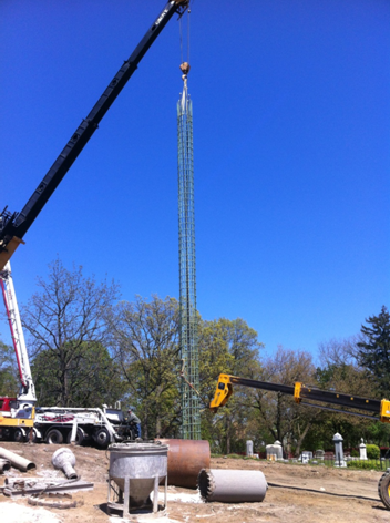
The Contractor may use concrete blocks at the bottom of the shaft to maintain concrete cover over the reinforcement. Ensure the Contractor picks and lowers the reinforcement cage into the shaft in a controlled manner, as not to cause racking or distorting of the tied cage. See Figure 8 for a typical reinforcement cage being lowered into the completed shaft.
Ensure the Contractor holds down the cage to control vertical displacement during concrete placement or casing extraction.
Placing Concrete
Ensure the Contractor places concrete as soon as possible after the excavation and reinforcement cage placement. If too much time has elapsed, loose or soft materials may accumulate at the bottom of the shaft, thus affecting the structural integrity. If this happens, direct the Contractor to remove the reinforcement cage, and remove loose or soft materials.
Use lighting to inspect the reinforcement cage and side of excavation for dry method construction. Ensure loose materials and groundwater is removed prior to placement of concrete.
Inspect by probing and measuring the shaft for wet method construction. The Contractor is required to place the concrete in one continuous operation starting from the bottom of the shaft. Once concrete reaches the top of the shaft, inspect the concrete for contaminants, and direct the Contractor to continue concrete placement until good quality concrete flows over the top of the shaft. The concrete should not be vibrated. Ensure the Contractor uses a sump or channel adjacent to the shaft to transmit displaced fluid and concrete away from the shaft opening. If polymer slurry is used, ensure the Contractor collects and disposes of the drilling fluids or polymer slurry appropriately.
Track the volume of concrete going into the shafts based on tickets, and perform theoretical concrete volume calculation based on the diameter and the length of the shaft. If the numbers vary by too much, it is possible a void is present.
Free Fall Concrete Placement
Free fall concrete placement can only be done in a dry shaft excavation.
The falling concrete cannot strike the sides of the excavation or the reinforcing cage. Ensure the Contractor uses a centering drop chute at least 3 feet long. If concrete strikes the sides of the excavation or the reinforcing cage, direct the Contractor to reduce the height of free fall, the rate of concrete flow, or both. The free fall height limit is 80 feet.
Tremie Tube Concrete Placement
Ensure the Contractor is using a tremie tube of at least 10 inches in diameter. Inspect the bottom of the Contractor’s tremie tube to ensure there is a bottom plate, valve, or plug so no water can get into the tube and contaminate the concrete prior to placement.
The tremie tube must be placed at the bottom of the shaft, and once the plate or plug is removed, or valve is opened, ensure the Contractor keeps the discharge end 5 feet to 10 feet immersed in concrete before raising the tremie tube. When initially starting the flow of concrete in the tremie pour, the end of the tremie tube must be within one tremie tube diameter of the base.
It is ideal for the concrete to be placed continuously until complete, however, should the Contractor need to withdraw the tremie tube from the concrete, ensure the discharge end is re-sealed, charged with concrete, and inserted back into the concrete at least 10 feet before continuing with the concrete placement.
For cased shafts, it is important discharge keep a head of concrete above the bottom of casing to be removed, and then remove the casing slowly, to allow the concrete to fill the annular space created by the case thickness. If the concrete level goes down during case extraction, direct the Contractor to stop the extraction, and add more concrete.
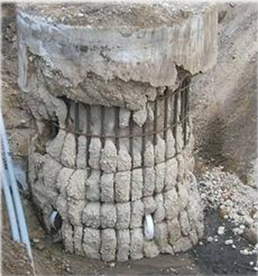
The concrete must be placed in a timely fashion, so the slump does not go below 4”, as the concrete will not properly envelope the rebar cage, or fill the shaft to the required diameter. See Figure 9 for an example of concrete not filling the required shaft diameter.
Allow the concrete to continue flowing at the top of the shaft, until quality concrete displaces all drilling fluid. Drilling fluid at the top of the shaft may have to be pumped of.
Ensure the Contractor provides a hand floated surface finish at the top of the shaft concrete per subsection 706.06.M.2 of the Standard Specifications for Construction.
- Do not remove the tremie tube from the concrete to take concrete QA samples.
Pumped Concrete Placement
Concrete can be pumped for by dry and wet shaft excavations, however, for use in wet excavations, ensure the Contractor provides a pump discharge tube with watertight joints.
Pumped concrete is very similar to tremie concrete in terms of operations. The main issue to watch is the sway and movement of the pumping pipes during concrete placement. Ensure the Contractor guides or anchors the pumping pipes as to not disturb already placed fresh concrete.
POST CONSTRUCTION INTEGRITY TESTING
Check the plans and specifications for any type of post construction integrity testing to be done on the completed shaft. There are several methods of non-destructive testing:
Pulse Echo Integrity Testing
This type of test involves setting an ultrasonic transducer on the surfaces of the concrete, which send wave pulses through the material. Wave pulses will continue through solid concrete until a concrete to air interface, at which time the pulse is reflected back to the transducer, and a depth can be measured. In the presence of voids, the wave would reflect back sooner than expected given the overall thickness of the materials.
Cross Hole Sonic Logging
This type of test involves the attachment of steel access tubes to the vertical cage rebar prior to concrete placement. The concrete is then placed and allowed to cure. Immediately after concrete placement, the steel access tubes are to be filled with water to protect from concrete infiltration. After curing, a sound source and a received are lowered into the steel access tubes, and while keeping them at the same elevation, sonic pulses are emitted from the sound source, and the wave generated is picked up by the receiver. Based on the speed the wave propagates through the material, the receiver maps the integrity of the surrounding concrete, and voids are reported where the wave returns to the receiver at faster rates than sound areas.
These types of tests are typically performed by a skilled technician, or MDOT prequalified consultant. The Geotechnical Services Section will be present during integrity testing to help analyze and interpret results.
Coring
Coring is a destructive test to remove cores of concrete from the finished shaft, and perform testing to determine concrete quality. Coring may also be done when voids are identified during non-destructive tests to reach the detected void. Grout can then be used to fill the void, and the core holes.
MEASUREMENT AND PAYMENT
-Reserved-
