719 - Earth Retaining Structures
GENERAL
Below is a list with definitions of common earth retaining structures utilized by MDOT:
- Abutment – A structure located at the end of a bridge span that supports the vertical loads from the bridge superstructure, and resists lateral loads from fill material on which the roadway rests immediately adjacent to the bridge.
- Anchored Wall – An earth retaining system typically composed of the same elements as non-gravity cantilevered walls and that derive additional lateral resistance from one or more tiers of anchors.
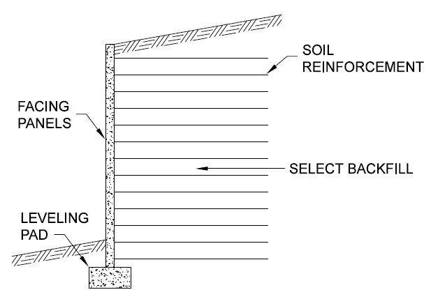
- Mechanically Stabilized Earth (MSE) Wall – A soil-retaining system, employing either strip or grid-type, metallic, or polymeric tensile reinforcements in the soil mass, and a facing element that is either vertical or nearly vertical.
- Segmental Block Retaining Wall – A soil-retaining system, typically employing polymeric tensile reinforcements in the soil mass attached to a facing element that consists of segmental blocks. Segmental blocks are typically dry cast blocks.
- Modular Block Retaining Wall – A soil-retaining system that consists of modular blocks stacked to form a gravity wall with a vertical or nearly vertical face. Modular blocks are typically large precast concrete blocks.
- Non-Gravity Cantilever Retaining Wall – A soil-retaining system that derives lateral resistance through embedment of vertical wall elements and supports retained soil with facing elements. Vertical wall elements may consist of discrete elements (piles, drilled shafts, etc.) or a continuous system (sheet piles, tangent drilled shafts, etc.).
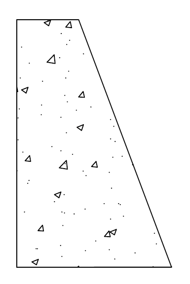
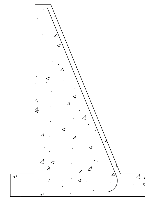
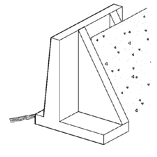
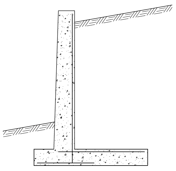
- Rigid Gravity and Semi-Gravity Retaining Wall – A structure that provides lateral support for a mass of soil and that owes its stability primarily to its own weight and to the weight of any soil located directly above its base.
Some of these elements may not be detailed on the plans, and may require shop drawing submittals for approval. See 707 of the MDOT Construction Manual for shop drawing requirements.
MATERIALS
-Reserved-
CONSTRUCTION
Abutments
MDOT utilizes the following types of abutments:
- Curtainwall Abutment (see rigid-gravity retaining wall below);
- Cantilevered Abutment (see semi-gravity retaining wall below)
- Integral and Semi-Integral Abutments – Integral and semi-integral abutments are detailed in the MDOT Bridge Design Guides 6.20.04, 6.20.04B, 6.20.04D.
Integral abutments are designed to be supported on a single row of piles that are oriented with their webs parallel to the bridge reference line to allow weak axis bending to accommodate superstructure articulation due to thermal gradient and live loading. Splices for piles in integral abutments must be complete joint penetration (CJP). Alternative mechanical splicer channels are not permitted.
Anchored Wall
Anchored walls can consist of ground anchors or tie backs. Verification load testing and proof load testing of the ground anchors is typically performed on all anchors to ensure the actual lateral pullout resistance is within the design tolerances. The verification load testing procedures will be detailed in the contract documents.
Mechanically Stabilized Earth Wall
Below are the basic components of a mechanically stabilized earth (MSE) wall system and a summary of items to review during construction:
- A. Subgrade Preparation – The Region Soils Engineer must be contacted to inspect the reinforced soil mass area plus 3 feet after the subgrade is prepared and before the wall is constructed. Subgrade undercutting may be required, depending on the recommendations from the Region Soils Engineer, and quantities in the contract documents.
- B. Precast Concrete Facing Panels, Corners and Copings – The Structural Fabrication Unit will coordinate with the project office to determine if these panels will be shop inspected. If they are shop inspected then each panel will have the MDOT approved for use stamp on them and they will be completely inspected (including material certifications and Buy America) by the Structural Fabrication Unit. If they are not shop inspected then verification of project requirements is the responsibility of the project office.
- Field inspectors must perform a visual inspection on the elements as soon as they are unloaded to check for signs of shipping or handling damage. The panels must also be properly stored on-site to prevent damage.
- C. Wire Facing Panels – Wire facing panels are typically specified for temporary MSE walls during Stage I construction. The walls end up being buried into the final structure and are not removed. The wire facing panels in this temporary application are usually black steel due to the short duration of use.
- D. Soil Reinforcement – MDOT permits the use of steel strip-type (bar or welded wire fabric ladder) reinforcement. Soil reinforcement must be placed as close to perpendicular from the wall face as practical. The reinforcement is permitted to be skewed around piling or other obstructions, but should be done so to not only reduce the skew, but also the number of skewed reinforcement strips. Reinforcement should not be in contact with other reinforcement. For skewed reinforcement soil must be placed between overlapping reinforcement.
- E. Bolts – Bolts are typically positioned with the head at the bottom side of the connection lug and the washer and nut on the top side. This allows the inspector to visually inspect that the washers and nuts have been installed as the reinforced soil is constructed behind the wall.
- F. Concrete Facing Panel Joint Material – Geotextile fabric is used to prevent soil particles from moving through the concrete facing panels. If the facing panel joints start to open up then the contractor should double the geotextile over the joints in question to provide additional protection.
- G. Backfill for Reinforced Soil Mass – Granular soil, typically Granular Material Class II, whic is free draining and meets the required strength and electro-chemical properties. This material must be tested and approved prior to placement.
- H. Leveling Pad – Is a non-reinforced concrete pad that provides a level starting point for constructing the precast concrete facing panels. A leveling pad is not needed for a wire faced MSE wall.
- I. Impervious Membrane – A polyvinylchloride (PVC) liner that prevents chloride laden runoff from penetrating into the reinforced soil mass and corroding the steel reinforcement. The liner must be shingle-lapped or seam welded and is positioned to slope away from the front of the wall and extend a minimum distance beyond the end of the soil reinforcement.
- J. CIP Copings – These copings are typically used as closure pours, but can also run up to 20 feet in length and can overlap adjacent panels without the need for a bond breaker. Expansion joint material is needed when butting CIP coping up to precast coping.
- K. Foundation Underdrains – Are strategically placed to transport water from the reinforced soil mass to a location far away from the wall. MSE walls are generally not designed for hydrostatic pressure. Foundation underdrains are to be installed at the locations indicated on the plans. The lower foundation underdrains are to be located as low as possible but still drain to either a ditch or a drainage structure.
MSE Wall Construction Considerations
- During the wet cure for the concrete bridge deck the water coming off of the deck needs to be collected and discharged away from the MSE wall. Water runoff from the deck may saturate the MSE backfill and cause wall movement.
- Groundwater needs to be controlled to prevent hydrostatic forces from acting on the wall. If groundwater is encountered during construction the location/number of foundation underdrains may need to be reevaluated.
- Compaction of the Select Backfill and any subgrade undercuts is important in order to limit any future settlement of the MSE wall fill.
Non-Gravity Cantilevered Retaining Wall
Examples of on-gravity cantilevered retaining walls are listed below:
- Tangent piles or drilled shafts;
- Drilled shafts or auger-cast piles spanned by structural facing (lagging, panels or shotcrete);
- Steel sheet piling (see Section 704 – Steel Sheet Piling and Cofferdams).
Rigid-Gravity and Semi-Gravity Retaining Wall
MEASUREMENT AND PAYMENT
-Reserved-
