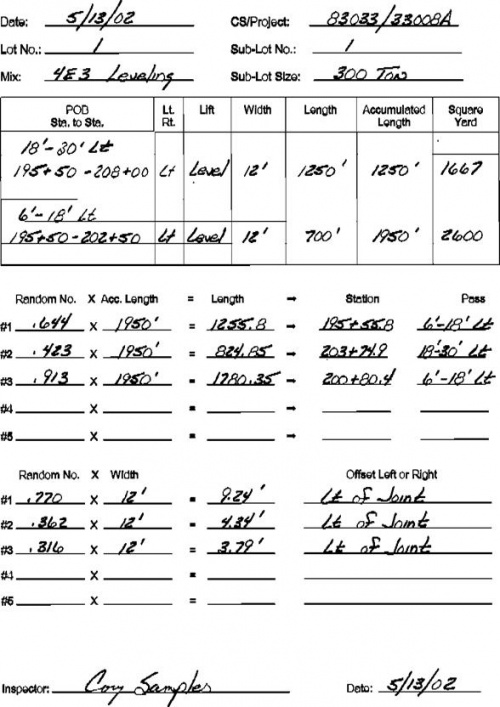
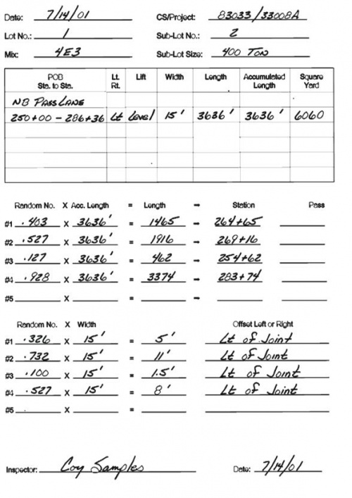
Difference between revisions of "501 - Plant Produced Hot Mix Asphalt"
JohnsonN23 (talk | contribs) m (→Documentation: relink) |
|||
| Line 4,130: | Line 4,130: | ||
|- | |- | ||
| | | | ||
| − | <center>[http:// | + | <center>[http://mdotjboss.state.mi.us/webforms/GetDocument.htm?fileName=1839.pdf 1839]</center> |
| | | | ||
Testing Of Bituminous Mixtures (Vacuum Worksheet) | Testing Of Bituminous Mixtures (Vacuum Worksheet) | ||
|- | |- | ||
| | | | ||
| − | <center>[http:// | + | <center>[http://mdotjboss.state.mi.us/webforms/GetDocument.htm?fileName=1903.pdf 1903]</center> |
| | | | ||
Daily Report of HMA Plant Inspection | Daily Report of HMA Plant Inspection | ||
|- | |- | ||
| | | | ||
| − | <center>[http:// | + | <center>[http://mdotjboss.state.mi.us/webforms/GetDocument.htm?fileName=1903B.pdf 1903B]</center> |
| | | | ||
Report of Quality Assurance Testing | Report of Quality Assurance Testing | ||
|- | |- | ||
| | | | ||
| − | <center>[http:// | + | <center>[http://mdotjboss.state.mi.us/webforms/GetDocument.htm?fileName=1903C.pdf 1903C]</center> |
| | | | ||
Daily Report of Contractor's Quality Control Tests | Daily Report of Contractor's Quality Control Tests | ||
|- | |- | ||
| | | | ||
| − | <center>[http:// | + | <center>[http://mdotjboss.state.mi.us/webforms/GetDocument.htm?fileName=1905.pdf 1905]</center> |
| | | | ||
Testing Of Bituminous Mixtures (Centrifuge Worksheet) | Testing Of Bituminous Mixtures (Centrifuge Worksheet) | ||
| Line 4,160: | Line 4,160: | ||
|- | |- | ||
| | | | ||
| − | <center>[http:// | + | <center>[http://mdotjboss.state.mi.us/webforms/GetDocument.htm?fileName=1907.pdf 1907]</center> |
| | | | ||
Report of Compacted Bituminous Mixture Core Density & Percent Compaction | Report of Compacted Bituminous Mixture Core Density & Percent Compaction | ||
| Line 4,175: | Line 4,175: | ||
|- | |- | ||
| | | | ||
| − | <center>[http:// | + | <center>[http://mdotjboss.state.mi.us/webforms/GetDocument.htm?fileName=1912.pdf 1912]</center> |
| | | | ||
Testing of Bituminous Mixtures Ignition Furnace Worksheet | Testing of Bituminous Mixtures Ignition Furnace Worksheet | ||
|- | |- | ||
| | | | ||
| − | <center>[http:// | + | <center>[http://mdotjboss.state.mi.us/webforms/GetDocument.htm?fileName=1923B.pdf 1923B]</center> |
| | | | ||
Sample Identification | Sample Identification | ||
Revision as of 09:33, 14 February 2017
GENERAL
Pre-Production Meeting
A pre-production meeting should be held before work commences on a project. During this meeting, the overall goals and expectations are set for the project. It is generally the responsibility of the Engineer to outline the scope of the project and to discuss the information provided in the contract documents. It is also the responsibility of MDOT and the Contractor to discuss any unusual aspects of the project, items that are not routine construction practices.
The role of each person on the project, for both MDOT and the Contractor, should be discussed and made clear. This requires that the supervisory personnel define the tasks, authority and responsibilities of each of the key individuals to be involved in the work. A list of MDOT personnel who will be assigned to the project should be provided to the Contractor.
The Contractor’s representative should be familiar with the project and be able to speak with authority about what is to be accomplished. A paving schedule for the project should be presented and discussed with MDOT. Any questions about the information in the contract documents should be raised and clarification requested, if necessary. A listing of key Contractor personnel who will be assigned to the project, with clear lines of authority, should be provided to MDOT.
Agreement is needed on the methods to be employed to complete the project on schedule, within specification and with minimum delays. A list of equipment that will be used on the project should be supplied to MDOT. Because continuity of the asphalt paving operation is critical to providing a quality pavement, the discussion between MDOT and the Contractor personnel should include such items as those listed below.
The discussion should include the safety of those individuals working on the project, as well as the safety of the traveling public. Clear responsibility for maintenance of all traffic control devices, such as signs, pavement markings and flagging, should also be defined.
The name of the individual responsible for safety for the Contractor should be provided to MDOT so that rapid and clear communications can be accomplished if safety problems occur. All personnel involved in the project must be required to comply with all safety standards applicable to the type of construction and asphalt paving work to be carried out.
Sampling methods and frequencies should be discussed. Test methods to be used should be reviewed to assure that individuals understand the purpose of each test, the location of the field lab and the personnel who are to conduct the tests, the time frame for the communication of the test results and the procedures to be used if failing test results are obtained. The details of the quality control program, both on the part of the Contractor and MDOT, should be discussed so that everyone is aware of who is responsible for performing the procedures and when they will be done.
Communication cannot stop once the pre-production meeting is concluded. It is important that the individuals in daily charge of the project for both MDOT and the Contractor meet periodically, both on a formal and informal basis, to discuss the progress and quality of the work done to date and the progress schedule for the future. Ideally, these meetings should occur at a regularly scheduled time and can be held on the project site, or at the asphalt plant. Asphalt paving projects, like many construction projects, are not always built as originally scheduled. Changes occur because of material supply, equipment breakdown, Contractor and Subcontractor schedules and weather conditions. When such changes do occur, it is important that they be communicated between the Contractor and MDOT and between MDOT and the Contractor.
|
| |
|---|---|
|
|
Project safety. |
|
|
Project mixture and testing Special Provisions. |
|
|
Job mix formula. |
|
|
Job mix formula adjustments, retroactive. |
|
|
Lot and sublot size. |
|
|
Random numbers. |
|
|
Sampling procedures. |
|
|
Laying out core locations and traffic control for coring. |
|
|
Laying out core locations, discuss how it will be done. |
|
|
Trial runs. |
|
|
Sequence of operations. |
|
|
Paving widths. |
|
|
Equipment required. |
|
|
Application rate of materials. |
|
|
Plant production and paver speed. |
|
|
Mixture temperature at the paver. |
|
|
Pavement density control, roller patterns. |
|
|
Weather and air temperature requirements. |
|
|
Project documentation. |
Safety
HMA mixtures consist of a blend of asphalt binder and aggregates mixed in an asphalt plant. When specified, special additives may be required.
The old saying “Safety is Everyone’s Business” is certainly true on an HMA paving project. Communication is one of the keys to a safe work environment. Every individual should know what is expected and know how to perform the assigned tasks. Everyone, regardless of title or job function, must be aware of the need for safe work practices. Occupational Safety and Health Administration regulations must be known, understood and followed by each person involved on the project. Safety talks are a very good way to start each day for both the Contractor and MDOT personnel. Several different organizations publish short, concise safety presentations that can be completed in two to three minutes. Daily talks are one way to continuously remind people that they are working in a potentially dangerous environment at both the plant and the paving site. If an unsafe work practice is noticed, corrective action should be taken immediately, even if the paving operation has to be shut down until the unsafe practice is corrected.
The people most likely to be hurt on an asphalt paving project are those individuals who are new to this type of work. A new plant inspector can easily get burned if not aware that asphalt samples are very hot. Functioning equipment parts, high temperatures, noise and moving delivery and haul trucks all add to the possibility of an accident occurring.
The street inspector can easily get hurt if they are not aware of the number of vehicles operating on the paving site. Individuals who are working around the paver are susceptible to being hit by passing traffic and have the potential to be hurt by the equipment being used in the paving operation.
Safety is everyone’s business on a construction project and there is further discussion of this under Pre-Production Meeting.
Glossary of Paving Terminology
|
| |||
|---|---|---|---|
|
|
|
|
|
|
|
|
|
|
|
|
|
|
|
|
|
|
|
|
|
|
|
|
|
|
|
|
|
|
|
|
|
|
|
|
|
|
|
|
- AGGREGATE - Various hard, inert materials such as sand, gravel, pebbles, etc., used as the bulk material in asphaltic mixes.
- ANGLE OF ATTACK - The angle incurred between the screed plate and the surface.
- ASPHALT - A mixture of bitumen (bonding agent) and aggregate (bulk material).
- AUGER - A rotating device with a broad, helical flange (flighting) used to spread paving material evenly in front of the screed.
- AUGER SHADOWS - Alternate dark and light areas of compaction occurring longitudinally in the mat, representing different density and texture.
- AUTOMATIC FEED CONTROLS - The standard system for maintaining a constant head of material in front of the screed by controlling the ON - OFF operation of the unit’s dual feed system.
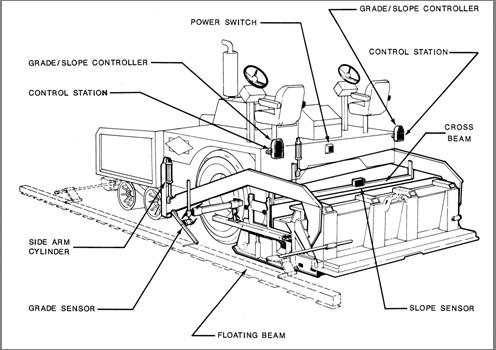
- AUTOMATIC GRADE AND SLOPE CONTROLS - The electronic/hydraulic control system that automatically maintains the elevation of one screed tow point with respect to a reference surface (grade), while maintaining the elevation of the opposite screed tow point in relation to the first with respect to gravity (slope). It is used to improve upon the levelability of the paver.
- AUTOMATIC LEVEL CONTROL (Joint Matcher) - An electronic/hydraulic control system that automatically controls the elevation of the mat being placed on one side with respect to a reference surface such as an adjacent mat or cut. It is used to match the profile of the edge of a mat to that of the adjacent surface.
- BITUMEN - A thick, viscous, petroleum-based substance used as bonding agent in asphaltic mixes.
- BURNERS - See SCREED HEATERS.
- COMPACTION - The process of increasing the density of paving material.
- CONVEYOR - An endless chain and bar assembly used to move paving material from the hopper to the auger.
- CORRUGATION - Washboard effect usually occurring in areas where braking and acceleration take place. It may also occur to a lesser degree in the even speed areas. It is caused by an excessively soft mix over an unstable base.
- CRACKS -
- ALLIGATOR - Crisscross cracks usually due to heavy traffic loads exceeding the strength of the surface over an unstable base.
- LONGITUDINAL - Cracks that appear along longitudinal joints, between lanes and shoulders, and many times at the base and outer edges of ruts. These cracks result from movement along these weakened areas.
- REFLECTION - Existing cracks in sub-pavement, eventually coming through an overlay, due to continued movement in the unstabilized sub-pavement.
- SHRINKAGE - Random cracks appearing due to lack of traffic that would normally keep the surface sealed.
- SLIPPAGE - Cracks appearing in the overlay because the surface is pushed or rolled apart by breaking traffic. This may also occur if an overlay is poorly bonded to the sub-pavement due to inadequate tack coating or improper mix design.
- TRANSVERSE - Cracks perpendicular to traffic flow. In overlays of concrete, the concrete joints may reflect through surface if movement occurs along the joint. Concrete stress cracks across the pavement may also reflect through.
- CROSS BEAM - A steel bar connected between the side arms for mounting the slope sensor.
- CROWN - The transverse contour of a finished mat. Also used to describe the contour of the screed plate. The transition line between two different slopes (i.e., between lanes or between lanes and shoulders).
- LEAD CROWN - The contour or profile from side to side of the leading edge of the screed.
- TAIL (or ROAD) CROWN - The contour of the trailing edge of the screed.
- NEGATIVE CROWN - Contour that is higher at the edges than at the center of a mat.
- POSITIVE CROWN - Contour that is higher at the center than at the edges of a mat.
- CUT-OFF SHOE - A detachable plate used to reduce the paving width of a screed.
- DENSITY - Measurement of in-place pavement compaction.
- DEPTH CRANK - Adjusting crank located at the rear of each side arm, used to control angle of attack of the screed.
- EDGER PLATE - A vertical plate at each end of the screed used to confine the head of material.
- ELEVATION - Vertical height from a reference surface.
- FEEDERS - L. H. and R. H. auger-conveyor systems on a paving machine.
- FLOATING BEAM - An aluminum beam, supported by a series of spring loaded shoes, towed beside the paver and used as a reference.
- FLOW GATES - Adjustable plates at the rear of the hopper used to control material volume conveyed to the augers.
- FLOOR PLATE - A heavy steel plate upon which the conveyors travel.
- FREE-FLOATING SCREED - The screed is supported on the surface of the paving material as it passes beneath the screed plate. Material thickness under the screed will increase or decrease according to the angle between the screed plate and grade surface.
- GRADE -
- The base surface (road bed) over which paving is being performed.
- The elevation of a fresh mat in relation to the base.
- The incline of a paving surface in the direction of travel, expressed by stating the rise or fall as a percentage of horizontal distance. (Example: 6 percent grade - 6 inches (6 m) of elevation change in 100 feet (100 m) of horizontal longitudinal run).
- GRADE CONTROL - A means of controlling the longitudinal elevation of a mat as it is being laid.
- GRADE SENSOR - An electrical device that detects positive and negative changes in longitudinal elevation from a grade reference (i.e., wire or string line, floating beam, mat reference, adjacent mat, or curb surface).
- HEAD OF MATERIAL - The volume of paving material directly in front of and along the entire lateral length of the screed.
- HMA - A paving material that consists of asphalt binder and mineral aggregate.
- HOPPER - The area at the front of the paving machine that receives the paving material.
- HYDRAULIC - Liquid in motion under pressure, the flow of which causes work to be accomplished.
- HYDROSTATIC TRANSMISSION - Power transmitted by a positive displacement pump through a liquid under pressure to a positive displacement motor.
- INCLINOMETER - See SLOPE SENSOR.
- JOINT - The point at which a new asphalt mat connects with one previously laid.
- LATERAL or TRANSVERSE JOINT - A joint perpendicular to the direction of travel (i.e., night joint).
- LONGITUDINAL JOINT - A joint parallel to the direction of travel (i.e., a joint between two "lanes" or between road and shoulder).
- TRANSVERSE JOINT - A joint perpendicular to the direction of travel.
- JOINT MATCHER - See AUTOMATIC LEVEL CONTROL.
- LIFT - Another term for “mat”, usually used in conjunction with a thickness, such as “a 6 inch (150 mm) mat was laid in [3] 2 inch (50 mm) lifts”.
- LINE OF SHEAR - The lateral line of contact in the paving material at the leading edge of the screed pre-strike-off where material divides to pass beneath the screed plate or move upward along the face of the screed into the augered material for later placement.
- MAT - The material being placed by a paver/finisher.
- MAT REFERENCE SYSTEM - An aluminum beam, supported by a series of spring loaded road wheels, which is towed behind the screed. It is used in conjunction with the Floating Beam to permit taking 50 percent of the longitudinal grade reference from the freshly laid mat and combining it with the average taken from the existing grade to produce the ultimate in a smooth riding surface.
- NULL - A condition that exists when components are at rest.
- “NULLED” SCREED - A screed resting flat on the mat and having no angle of attack.
- “NULLED” GRADE AND SLOPE SENSOR - Sensors that are operating, however, they are transmitting no signal.
- PIVOT POINT (of screed) - The pin mounting point of the screed frame on the rear of the side arm.
- POT HOLES - Local base failure causes a pocket that further deteriorates due to containment of water as the surface collapses. Traffic bounces the broken surface out, exposing intermediate and base materials to more moisture and the abrasion of traffic.
- PULL POINTS - See TOW POINTS.
- PUSH ROLLER - Rollers mounted at the front of the paver to provide contact area between the paver and the asphalt truck tires.
- PRE-STRIKE-OFF SHIELD - The vertical plate at the front of the screed that meters material passing beneath the screed.
- QUARTER POINTS - Points on the screed midway between the center and the ends.
- RAVELING - Road surface chunks away producing a very rough riding surface. Edges of pavement may completely disintegrate. The causes are usually the same as stripping, but also may include deficient mix design.
- RIDEABILITY - Perceived smoothness of the finished road surface.
- RIPPLES - Short frequency changes in the elevation of a mat surface.
- RUTS - Troughs in the wheel tracks caused by increased compaction and/or stripping due to heavy traffic.
- SCREED - The assembly towed behind the tractor, that strikes off, smooths and exerts some pre compaction on the paving material being placed.
- SCREED EXTENSIONS - Attachments for increasing screed width.
- SCREED HEATERS (Burners) - The devices that preheat the screed plate to a temperature approximately that of the material to be laid.
- SCREED PLATE - The bottom plate of the screed.
- SHOVING BULGE - Pavement that has been pushed by braking vehicles or roller.
- SLOPE - The incline of a paving surface perpendicular to the direction of travel expressed by stating the rise or fall as a percentage of horizontal distance. (Example: 2 percent slope - 2 inches (50 mm) of elevation change in 100 feet (250 mm) of lateral run).
- SLOPE CONTROL - A means for controlling the transverse elevation of the fresh laid mat in relation to the grade.
- SLOPE SENSOR (Inclinometer) - An electrical device that detects positive and negative changes in lateral elevation using the grade controlled side of the machine as a reference.
- STRIPPING - Road surface peels away producing a rough, open texture. It is usually due to debonding between the asphalt and aggregate. The cause may be heavy traffic and moisture, or lack of density (full specification compaction) when placed.
- TOW LENGTH - The distance from the two point (at the front of the side arm) to the pivot point (of the screed).
- TOW POINTS (Pull Points) - The points where the side arms of the screed are attached to the tractor unit.
- UPHEAVAL - Swelling of sub-pavement caused by excessive heat or freezing expansion of trapped water beneath the surface.
- VIBRATORS - A rotating shaft and eccentric weight assembly mounted on the screed that produces vibration.
- WAVE - Long repeating changes in the elevation of the mat surface.
MATERIALS
It is very important to know what special provisions are contained in the proposal. Mixture types to be used and the sampling and testing procedures vary depending on the specifications used.
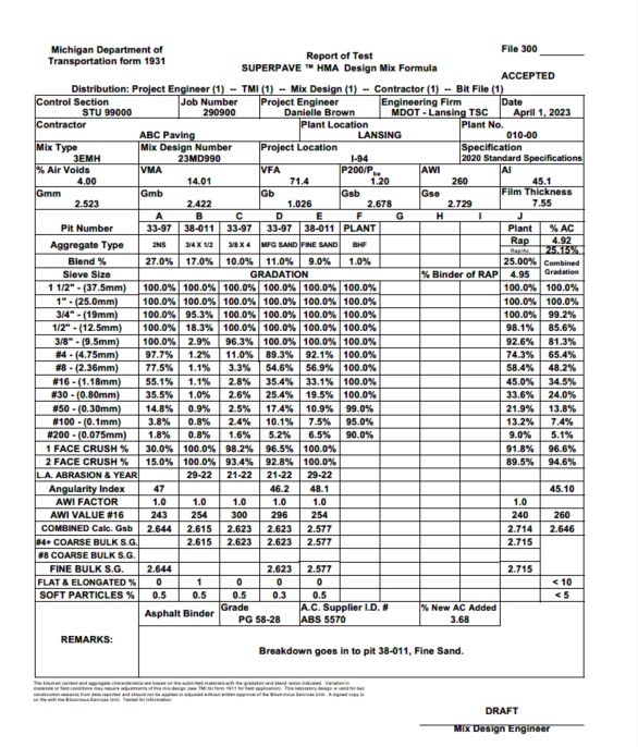
The materials used in the HMA mixtures will be shown on Form 1931 HMA Mix Design (Figure 501-1), and those materials will meet the requirements as specified in Tables 501-1, 501-2 and 904-2 of the Standard Specifications for Construction.
All mixtures specified for a project must have an approved mixture design before mix production can proceed.
The Contractor must submit a mixture design to the MDOT Construction Field Services laboratory for approval in accordance with the HMA Production Manual.
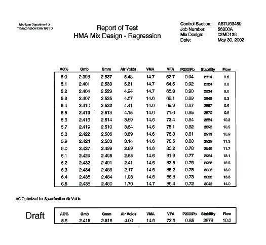
The field application of the applied mix design is called the Job Mix Formula (JMF), (Figure 501-2). Adjustments to the JMF will not be allowed outside the mixture limits shown in Tables 501-1 and 501-2 of the Standard Specifications for Construction.
Hot Mix Plants
HMA mixtures being supplied to MDOT projects must be produced at a certified facility. Plants are certified in accordance with the HMA Production Manual. This certification includes the approval of the field laboratory used for acceptance testing, the Contractor’s quality control plans (which should be available at the plant) and other plant operational requirements. The certification is normally completed by the Region Traveling Mixture Inspector (TMI) before the Contractor starts his first project in the spring. Certifications are good for one construction season only.
The function of the hot mix plant is to heat the aggregates, add the asphalt cement and produce a homogenous asphalt mixture. The aggregate used to make the mix can be a single aggregate, but it is generally different sizes blended together through the cold feed bins to produce proper gradation. Asphalt cement is the material that holds the aggregate together. This material can be “neat”, unmodified or modified with polymers, rubber, latex, etc. These asphalt cements may also contain anti-strip agents.
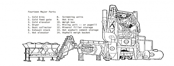
There are two basic types of asphalt mixing plants. The majority of plants used are known as drum mix plants; the other, less frequently used type, is a batch plant. The batch plant consists of the cold feed system, individual bins that hold and feed the aggregate to the drum dryer (Figure 501 3). This dryer heats the aggregate to the desired temperature and delivers the material to the hot bins in the tower unit. Aggregate is generally sized by means of a screen deck into two to four of these hot bins. The aggregates are then proportioned by weight into the mixer, also called the pug mill. After a short mixing process, the asphalt cement is added and the entire mixture is mixed for 30 to 45 seconds. The mix is then dumped into a truck, or transferred to a hot storage silo to be loaded into a truck later.
Drum mixers come in many different types, such as parallel flow, counter flow, double barrel, drum-within-a-drum and drums with separate mixing chambers (Figure 501-4). Most drum mixer plants heat the aggregate, add the asphalt cement and recycled asphalt pavement (RAP), if used, and mix all the ingredients in the same drum. The other type adds the asphalt cement and RAP in a separate mixing chamber out of direct contact with the burner flame. No matter what type of plant is being used, several key items should be monitored.
|
| |
|---|---|
|
|
The aggregate stockpiles should be built on a clean, dry and stable foundation, with positive drainage. The stockpiles shall be large enough to supply a project continuously and consistently. |
|
|
Aggregate of different sizes should be stockpiled separate from one another. |
|
|
When using drum mix plants, the aggregate moisture content of each stockpile should be taken at least once a day and the number entered into the plant control system. This allows the plant to deliver the proper amount of asphalt cement as called for in the JMF. |
|
|
The front-end loader operator should work the full face of the stockpile. |
|
|
A scalping screen should be placed in the aggregate cold feed charging system and the RAP feed system to remove any oversize material. |
|
|
The weigh bridges on the cold feed and RAP charging conveyors must be calibrated. |
|
|
The asphalt cement in the storage tanks should be kept at a constant temperature, normally between 275°F and 311°F . The asphalt tanks and all hot asphalt lines should be insulated. |
|
|
The asphalt cement delivery system must be calibrated. |
|
|
Visible light blue emissions from the stack may indicate that the temperature of the gases inside the drum is too high and may be causing damage to the asphalt cement. |
|
|
The trucks should not be loaded by slowly driving forward while the mix is being delivered from the silo. Multiple drops of the mix are necessary. |
Plant Procedures
Every HMA paving project must have an approved mix design for each mixture used on the project. The design may have been approved for another project; however, a JMF must be prepared for each mixture used on the project. The JMF is prepared and signed by the TMI. After production begins, the Contractor may ask for JMF adjustments. These adjustments may be allowed if there is reason for the request and as long as the resulting mixture meets the specifications for the project.
It is the Contractor’s responsibility to provide quality control necessary to produce the mixture uniformly, within the limits specified in 12SP501(U) Superpave Hot Mix Asphalt Percent Within Limits (PWL) or 12SP501(V) Superpave Hot Mix Asphalt Percent Within Limits (PWL) For Capital Preventive Maintenance (CPM) Mill & Resurface Projects and CPM One Course Overlay Projects. It is MDOT’s responsibility to conduct quality assurance and verification sampling and testing to ensure conformity of the mix to 12SP501(U) Superpave Hot Mix Asphalt Percent Within Limits (PWL) or 12SP501(V) Superpave Hot Mix Asphalt Percent Within Limits (PWL) For Capital Preventive Maintenance (CPM) Mill & Resurface Projects and CPM One Course Overlay Projects.This testing is done at the field laboratory provided by the Contractor located at the asphalt plant or at an MDOT Region Lab.
The MDOT plant inspector should follow the sampling and testing procedures explained in the Special Provision 12SP501(U) Superpave Hot Mix Asphalt Percent Within Limits (PWL) or 12SP501(V) Superpave Hot Mix Asphalt Percent Within Limits (PWL) For Capital Preventive Maintenance (CPM) Mill & Resurface Projects and CPM One Course Overlay Projects. It can also be provided by the TMI.
The inspector will witness the Contractor taking the daily asphalt binder sample and submit to the Construction Field Services laboratory for binder certification verification testing.
Note
HMA types will be as specified on the plans or in the proposal.
Bond coat, also referred to as tack coat, is an asphalt emulsion. This is a certified product and the suppliers must be on the Certified Products List.
CONSTRUCTION
The Contractor must provide all equipment required to prepare the base and place the HMA in accordance with the plans and specifications. This equipment must be safe, environmentally acceptable and capable of producing a specification product. The typical equipment used:
|
|
|
|---|---|
|
Cold-milling machine |
Used to remove old pavement. |
|
Pressure distributor |
Used for applying the bond coat. |
|
HMA paver |
Used for placing and spreading the HMA. |
|
Rollers |
Used for compacting the HMA pavement. |
|
Hauling units, Trucks |
Used for hauling the mix from the plant. |
|
Sweepers |
Used for cleaning the old surface to be paved. |
|
Misc. equipment |
Hand tools, level, straightedge and boards. |
This equipment should be thoroughly checked before using it on the project. The inspector may use the following checklist to record the condition of equipment. This checklist may be placed in the project files.
|
Paver Checklist | |||
|---|---|---|---|
|
|
Yes |
No |
Remarks |
|
Is the automation operating properly? |
|
|
|
|
Is the auger control operating properly? |
|
|
|
|
Are the vibrators on the screed operating properly? |
|
|
|
|
Does the paver have reverse pitch augers or paddles at center of paver? |
|
|
|
|
Do extensions have proper vibratory action? |
|
|
|
|
Does paver have properly working screed heaters? |
|
|
|
|
Do extensions have approved method of heating? |
|
|
|
|
Is automation ski in good condition? |
|
|
|
|
Is the automation ski of proper length 30 feet +/- for all courses except last pass top course? |
|
|
|
|
10 feet +/- for last pass top course? |
|
|
|
|
Does the paver have two operating warning lights? |
|
|
|
|
Roller Checklist - Manufacturer and Roller Number -______________________________________ | |||
|---|---|---|---|
|
|
Yes |
No |
Remarks |
|
Does the Contractor have proper number of rollers? |
|
|
|
|
Are the rollers of proper size? |
|
|
|
|
Are the rollers free from backlash? |
|
|
|
|
Do the rollers steer properly? |
|
|
|
|
Are the king bolts in good condition on steel wheeled rollers? |
|
|
|
|
Are the water sprinklers in good operating condition? |
|
|
|
|
Are the mats or wheel scrapers in good operating condition? |
|
|
|
|
Are roller wheels free of openings or projections? |
|
|
|
|
Do vibratory rollers have automatic shutoff when speed is less than .5 mph? |
|
|
|
|
Can VPM be locked in on vibratory rollers? |
|
|
|
|
Can speed be locked in on vibratory rollers? |
|
|
|
|
Do pneumatic rollers have a min. of seven wheels? |
|
|
|
|
Is tire pressure as specified? |
|
|
|
|
Do the rollers have an operating warning light? |
|
|
|
|
Distributor Checklist - Manufacturer and Distributor Number -______________________________ | |||
|---|---|---|---|
|
|
|
|
|
|
Is distributor mounted on proper vehicle? |
|
|
|
|
Is vehicle tachometer working properly? |
|
|
|
|
Is distributor tachometer working properly? |
|
|
|
|
Does the distributor have a capacity of at least 800 gallons (3,000 liters)? |
|
|
|
|
Are flasher lights working properly? |
|
|
|
|
Are circulating systems working properly? |
|
|
|
|
Is heating system in good working condition? |
|
|
|
|
Is thermometer in tank working properly? |
|
|
|
|
Is tank clean? |
|
|
|
|
Is spray bar clean? |
|
|
|
|
Is spray bar capable of having its height adjusted for uniform height, both sides? |
|
|
|
|
Are nozzles proper size? |
|
|
|
|
Are nozzles clean? |
|
|
|
|
Is hand spray working properly? |
|
|
|
|
Are fluid connections free of leaks? |
|
|
|
|
Are nozzles set at proper angles |
|
|
|
|
Are guards placed on end of spray bar to protect over spray where necessary? |
|
|
|
|
| |||
|---|---|---|---|
|
|
|
|
|
|
Do all trucks have working backup warning systems? |
|
|
|
Cold-Milling Machine
Cold-milling machines shall be equipped with an automatically controlled and activated cutting drum that is capable of grade reference, maintaining transverse slope control and producing a uniformly textured surface. An approved grade referencing attachment, not less than 30 feet in length, may be used. This equipment must be capable of accurately removing the pavement surface, in one or more passes, to the required grade or cross section.
Hauling Units
|
| |
|---|---|
|
|
Water repellent. |
|
|
Of sufficient weight and strength to resist tearing. |
|
|
Be in good condition with no holes or tears. |
|
|
Large enough to cover the top of the load and extend over sides and tailgate. |
|
|
Enough tie-down points to secure properly and prevent flapping. |
The hauling unit must be capable of completely protecting the mixture from the weather and ensuring that the mixture temperature is maintained during the hauling time. A release agent may be applied to the surfaces of the truck or trailer bed. Fuel oil is not to be used as a release agent.
Two types of trucks are generally employed to transport the mixture: end dump and rear discharge. These trucks are loaded in the same manner directly from the silo at the plant. If temperatures warrant, the sides and bottom of the truck bed should be insulated. The insulation should be tight against the body of the bed; there should be no gaps between the side of the truck and the insulation through which air could move.
Every haul truck should be equipped with a tarpaulin, which can be employed as needed to protect the mix in case of inclement weather.
Pressure Distributor
Pressure distributors are used to apply a uniform application of the asphalt emulsions, normally referred to as the tack or bond coat. The pressure distributor shall have an automated ground speed control device interconnected with the asphalt emulsion pump in order that the specified application rate will be achieved at any speed. It shall be capable of maintaining the asphalt emulsion at the specified temperature. The spray bar nozzles shall produce a uniform fan spray, and the shutoff shall be instantaneous, with no dripping. Each pressure distributor shall be capable of maintaining the specified application rate within +/- 0.015 gallons/square yard for each load.
Paver
Pavers spread the hot mix asphalt to the desired width and thickness and produce a smooth, uniform mat texture. The paver consists of two primary parts, the tractor unit and the screed unit.
The tractor unit provides the motive power to the paver and to transfer the mixture from the receiving hopper on the front of the paver to the spreading augers at the back of the paver. The second unit is the paver screed. This leveling device is attached to the tractor unit at only one point on each side of the paver; it is able to float on the asphalt mixture and to provide initial mat texture and compaction to the material as it passes under it.
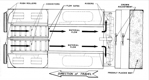
The tractor unit receives the asphalt mixture from the haul trucks, carries that mixture back to the spreading augers, distributes the mixture across the width of the screed and pulls the screed over that mixture. The tractor unit is powered by its own engine and provides the power to move the paver forward, either on rubber tires, or crawler tracks. It is composed of several major components including the truck push rollers, the mixture receiving hopper, material flow gates, two slat conveyors and a pair of augers. See Figure 502-1.
The paver screed is a leveling device attached to the tractor unit at only one point on each side of the paver; it is able to float on the asphalt mixture and to provide initial mat texture and compaction to the material as it passes over it.
Push Rollers
The truck push rollers, located on the front of the paver hopper, are used to maintain contact with the tires of the truck and to push the truck ahead of the paver. The rollers must be clean and free to rotate to allow smooth forward travel of the paver. If the push rollers are not cleaned periodically and do not rotate freely, the truck tires will slide on the rollers and increase the load on the paver.
Moreover, if one roller rotates freely and the other does not, the paver may tend to change direction. Many pavers are equipped with a truck hitch that is located beside the push rollers. This hitch acts to keep the truck in contact with the paver to prevent the truck driver from inadvertently pulling away from the paver and dumping mix on the pavement in front of the paver. The hitch is controlled by the paver operator. Once the truck bed has been emptied of mix, the truck hitch is withdrawn and the truck is able to pull away from the paver.
Paver Hopper
The paver hopper is used to receive and temporarily hold the mixture from the trucks. The front of the hopper must be constructed in a way to minimize the spillage of mix from the hopper. The sides, or wings, of the hopper are movable. Mixture, if left to stand for a long time in the corners of the hopper, will cool. To minimize mat problems, the paver operator should dump the wings as little as possible. The paver hopper must be at least half full at the time the wings are dumped. The slat conveyors in the bottom of the hopper should not be visible when the wings are emptied. Keeping the hopper at least half full between truckloads of mix keeps the head of mix in front of the screed constant and this will reduce mat problems.
Slat Conveyor
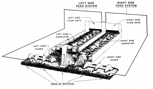
At the bottom of the paver hopper is a set of slat conveyors. These devices are used to carry the mixture from the hopper through the paver tunnel to the back of the paver and the spreading augers. The slat conveyor on one side operates independently from the movement of the other side. Thus, the amount of mixture that can be carried back to the augers on one side can be different from the other side. This allows the paver operator to feed more or less mixture to either side of the paver. This is helpful at lane tapers, crown corrections, or in areas of wedging. See Figure 502-2.
Flow Gates
At the back of the paver hopper, and over each slat conveyor, is a set of gates. These gates are used to regulate the amount of mix that can be delivered by the slat conveyors to the augers. The gates move vertically, either manually or mechanically. Depending upon the gate settings, more or less mixture is permitted to enter the tunnel. The flow gates should be adjusted to provide a uniform head of material in front of the screed. See Figure 502-2.
Augers
The mix that is carried to the back of the tractor unit by the slat conveyors is deposited in front of the augers. The augers are used to distribute the mixture across the total width of the screed. The auger on each side of the paver is operated independently of the other. The auger and the slat conveyor on the same side must be operated together. At the junction of the two augers in the center of the paver, adjacent to the auger gear box, there should be a reversed pitch auger, or paddle, to tuck the mixture under the gear box and assure that the mixture at this location is the same as that across the rest of the screed. It is important that the augers carry a consistent amount of mix across the front of the screed so that the pressure on the screed is kept as constant as possible.
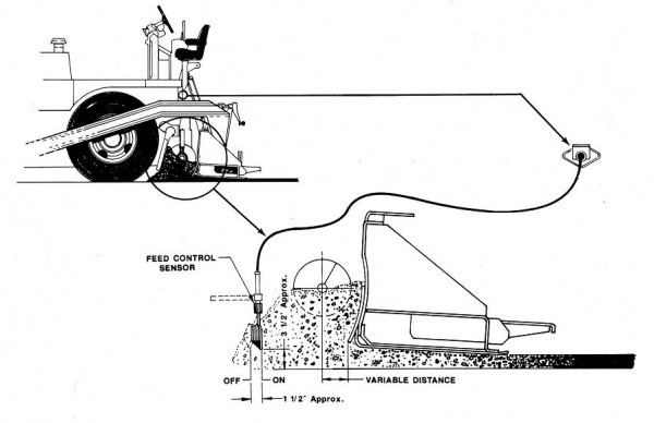
All pavers are equipped with an automatic feed system that, when properly adjusted, supplies mixture to the paver screed to maintain a uniform head of material. For this system, a feed control sensor is used to determine the amount of mix in the auger chamber. If the volume of the mix in front of the screed falls below the desired amount, the feed sensor will engage the slat conveyors and auger system, pulling more mix back to the screed area. See Figure 502-3.
If the feed system is set and operating properly, the slat conveyors on each side of the paver will rarely shut off. This continuous action of the slat conveyors and augers is accomplished by setting the proper position for the hopper flow gates and determining the correct speed setting for the slat conveyors and augers. Intermittent operation of the slat conveyors and auger system could cause both auger shadows and ripples in the mat behind the screed.
Screed Unit
The screed unit, which is towed by the tractor unit, establishes the thickness of the asphalt layer and provides the initial mat texture. In addition, the screed imparts a level of compaction with the vibratory action of the screed. The screed is attached to the tractor unit at only one point on each side of the paver. This point is called the tow or pull point. This floating screed principle is employed on all modern pavers in use today.
This principle allows the paver screed to average out changes in grade that are experienced by the tractor wheelbase. For the floating screed principle to work properly, it is important that the pull points on both sides of the tractor be at the same level above the ground.
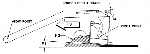
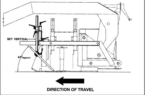
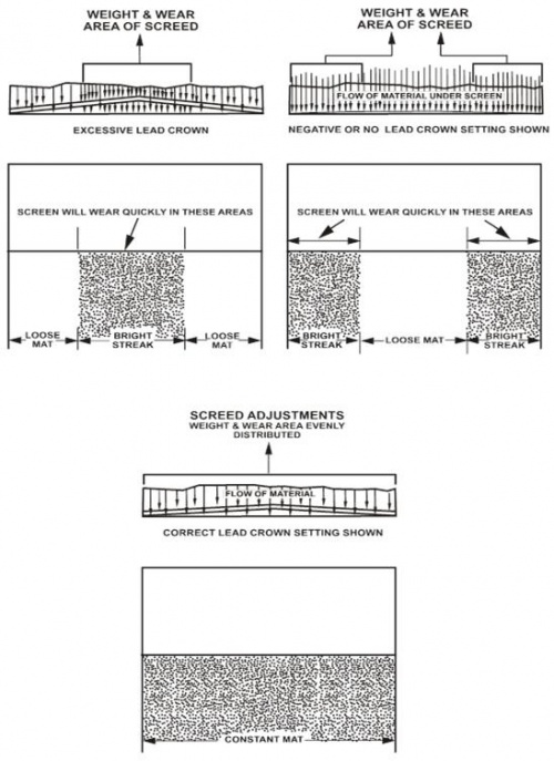
The combination of the screed pull point at the end of the leveling arm and the thickness control device at the screed provides for adjustments to be made to the angle of attack of the screed. See Figure 502-4.
F2 - Head of Material
F3 - Paving SpeedThe screed is continually attempting to keep in balance all the forces acting on it. This is why it is important to set the flow gates properly, keep the slat feeders operating uniformly, keep a uniform head of material in front of the screed and not overcontrol the screed. The temperature of the mix must be kept uniform so that the viscosity of the mix does not change and influence the balance of forces acting on the screed. When a change in one force occurs, the screed will rise or fall and will change the thickness of the mat being placed.
The screed should be raised and the bottom surface checked for smoothness, twisting, and excessive wear. Screed plates first wear out about four to six inches from the trailing edge.
Paver Speed
The speed of the paver should be adjusted to give a uniform texture and coordinate satisfactorily with the rate of delivery of the mixture to the paver to provide a uniform placement rate, without intermittent operation of the paver. Paver speed is a large contributor to the smoothness of the ride on a finished pavement. Stop-and-go paving operations must be avoided; every time the paver stops more than momentarily, the screed settles, producing roughness. See Figure 502-5 for paver speed based on yield and plant production rates.
The paver speed has a major effect on the forces acting on the screed. It is good practice to keep the speed of the paver as constant as possible during the paving operations. When changing trucks, it would be best if the transfer could be done without slowing or stopping the paver. At relatively slow paving speeds, it might be possible to make the truck exchange while keeping the head of material constant. This requires the level of mix in the hopper to be kept at least even with the bottom of the flow gates. If the normal paving speed is fast, or the truck exchange is slow, it will be better to stop the paver when the transfer of trucks occurs. When one truck is emptied, it should pull away from the paver. The paver should be brought from paving speed to a stop as quickly and as smoothly as possible without jerking the paver. The next truck should then be backed toward the paver, stopping short of the paver. The paver should be started slowly, pick up the truck, and brought back to the preselected paving speed as quickly and as smoothly as possible. This procedure will minimize the change in forces acting on the screed and will result in a near-constant mat thickness.
Paver speed for various production and application rates can be calculated using the following equations or selected from Figure 502-5.
- V = [(Rp)(L)]/60
- L = 2000/9WA
- where:
- V = paver speed (feet/minute)
- Rp = plant production rate (ton/hour)
- L = length of pavement (feet) placed per ton of mix
- 60 = converts from hours to minutes
- W = width of pavement (feet)
- A = application rate or yield (pounds/square yards)
- 2000 = converts from tons to pounds
- 9 = converts from feet to square yards
- Example -
- Given:
- Application Rate (A) = 165 pounds/square yards
- Width of Pavement (W) = 11 feet
- Plant Production Rate (Rp) = 300 ton/hour
- Find: Paver Speed (V)
- First find the length of 11 foot (3.35 m) width pavement that can be placed per ton of mix.
- L = 2000/9WA = 2000/[9(11)(165)] = 10 feet/ton of mix
- Next calculate the paver speed.
- V = RpL/60 = [(300 ton/hr)(10 ft/ton)] / 60 min/hr = 50 ft/min
|
Figure 502-5 - Paver Speed PLANT PRODUCTION (TONS PER HOUR) YIELD IS POUNDS PER SQUARE YARD | |||||||||||||||
|---|---|---|---|---|---|---|---|---|---|---|---|---|---|---|---|
|
|
|
|
|
|
|
|
|
|
|
|
|
|
|
|
|
|
|
|
|
|
|
|
|
|
|
|
|
|
|
|
|
|
|
|
|
|
|
|
|
|
|
|
|
|
|
|
|
|
|
|
|
|
|
|
|
|
|
|
|
|
|
|
|
|
|
|
|
|
|
|
|
|
|
|
|
|
|
|
|
|
|
|
|
|
|
|
|
|
|
|
|
|
|
|
|
|
|
|
|
|
|
|
|
|
|
|
|
|
|
|
|
|
|
|
|
|
|
|
|
|
|
|
|
|
|
|
|
|
|
|
|
|
|
|
|
|
|
|
|
|
|
|
|
|
|
|
|
|
|
|
|
|
|
|
|
|
|
|
|
|
|
|
|
|
|
|
|
|
|
|
|
|
|
|
|
|
|
|
|
|
|
|
|
|
|
|
|
|
|
|
|
|
|
|
|
|
|
|
|
|
|
|
|
|
|
|
|
|
|
|
|
|
|
|
|
|
|
|
|
|
|
|
|
|
|
|
|
|
|
|
|
|
|
|
|
|
|
| |||||||||||||||
|
|
|
|
|
|
|
|
|
|
|
|
|
|
|
|
|
|
|
|
|
|
|
|
|
|
|
|
|
|
|
|
|
|
|
|
|
|
|
|
|
|
|
|
|
|
|
|
|
|
|
|
|
|
|
|
|
|
|
|
|
|
|
|
|
|
|
|
|
|
|
|
|
|
|
|
|
|
|
|
|
|
|
|
|
|
|
|
|
|
|
|
|
|
|
|
|
|
|
|
|
|
|
|
|
|
|
|
|
|
|
|
|
|
|
|
|
|
|
|
|
|
|
|
|
|
|
|
|
|
|
|
|
|
|
|
|
|
|
|
|
|
|
|
|
|
|
|
|
|
|
|
|
|
|
|
|
|
|
|
|
|
|
|
|
|
|
|
|
|
|
|
|
|
|
|
|
|
|
|
|
|
|
|
|
|
|
|
|
|
|
|
|
|
|
|
|
|
|
|
|
|
|
|
|
|
|
|
|
|
|
|
|
|
|
|
|
|
|
|
|
|
|
|
|
|
|
|
|
|
|
|
|
|
|
|
|
|
|
| |||||||||||||||
|---|---|---|---|---|---|---|---|---|---|---|---|---|---|---|---|
|
100 |
125 |
150 |
175 |
200 |
225 |
250 |
275 |
300 |
325 |
350 |
375 |
400 |
425 |
450 | |
|
100 |
20 |
25 |
30 |
35 |
40 |
45 |
50 |
55 |
60 |
65 |
70 |
75 |
80 |
85 |
90 |
|
110 |
18 |
23 |
28 |
32 |
37 |
41 |
45 |
50 |
55 |
59 |
64 |
68 |
73 |
77 |
82 |
|
120 |
17 |
21 |
25 |
29 |
33 |
36 |
42 |
46 |
50 |
54 |
58 |
63 |
67 |
71 |
75 |
|
130 |
15 |
19 |
23 |
27 |
31 |
34 |
38 |
42 |
46 |
50 |
54 |
58 |
62 |
66 |
69 |
|
140 |
14 |
17 |
21 |
25 |
29 |
32 |
36 |
39 |
43 |
46 |
50 |
53 |
57 |
61 |
65 |
|
150 |
13 |
16 |
20 |
23 |
27 |
30 |
33 |
36 |
40 |
43 |
47 |
50 |
53 |
56 |
60 |
|
160 |
12 |
15 |
19 |
22 |
25 |
28 |
31 |
34 |
38 |
41 |
44 |
47 |
50 |
53 |
56 |
|
170 |
12 |
15 |
18 |
20 |
23 |
26 |
30 |
33 |
36 |
38 |
41 |
44 |
47 |
50 |
53 |
|
180 |
11 |
14 |
17 |
19 |
22 |
25 |
28 |
31 |
34 |
36 |
39 |
42 |
45 |
47 |
50 |
|
190 |
10 |
13 |
16 |
19 |
21 |
23 |
26 |
29 |
32 |
34 |
37 |
39 |
42 |
44 |
47 |
|
200 |
10 |
12 |
15 |
18 |
21 |
22 |
25 |
28 |
30 |
32 |
35 |
38 |
40 |
42 |
45 |
|
210 |
9 |
11 |
14 |
17 |
19 |
21 |
24 |
26 |
29 |
31 |
33 |
35 |
38 |
40 |
43 |
|
220 |
9 |
11 |
14 |
16 |
18 |
20 |
23 |
25 |
28 |
30 |
32 |
34 |
37 |
39 |
41 |
|
| |||||||||||||||
|---|---|---|---|---|---|---|---|---|---|---|---|---|---|---|---|
Screed Heaters
The screed is equipped with heaters, the purpose of which is to increase the temperature of the cold bottom screed plate to about 320°F (160°C). A properly heated screed, particularly at the start of the day’s paving operations, or after any extended shutdown of the paving process, provides a more uniform mat surface texture. It is necessary for the screed to be the same temperature as the mixture being placed in order to assure that the mix does not stick to the screed plate and tear the mat, causing a rough texture to the surface. To preheat the screed, the heaters are normally operated for a period of 10 minutes to 20 minutes before the commencement of the paving operation. Care should be taken to avoid overheating, which can cause permanent warping of the screed.
Crown Control
The screed on the paver can be angled at its center to provide for positive or negative crown. The amount of crown that can be introduced into the screed varies with the width of the basic screed and with the make and model of the equipment. When rigid extensions are being used in conjunction with the main screed, the crown can usually be altered at any of the points where the extensions are joined. If a hydraulically extendable screed is being used with the paver, the crown can be introduced in the center of the main screed and also at the points between the main screed and the hydraulic extensions.
Vibrators
The amount of compaction imparted to the asphalt mixture is a function of many variables. Two factors within the screed itself can contribute to the degree of compaction. The first is the frequency of vibration and the second is the amplitude of the compactive effort. The frequency of vibration is controlled by the rotary speed of the vibrator shaft. The applied amplitude is determined by the location of the eccentric weights that are located on the shaft. In general, the vibrators should be used near the maximum possible frequency.
The density obtained by the paver screed is also a function of the speed of the paver. The faster the paver moves, the less time the screed sits over any particular point in the new mat, thus the amount of compactive effort applied by the screed decreases. For asphalt mixes, it can be expected that about 70 percent to 80 percent of the theoretical maximum density may be obtained as the mixture passes under the screed.
Extensions
When the basic width of the paver screed needs to be changed to accommodate increased paving widths, rigid or hydraulic screed extensions can be employed. Rigid extensions come in several widths, usually 6 inch, 12 inch, 2, 3, and 5 foot sections.
Rigid Extensions
In order to keep the paver in balance, where possible, the width of the rigid extensions added should be approximately equal on both sides of the screed. It is important for the screed extension to be attached securely to the main screed. Further, the extension must be set at the same elevation and angle as the basic screed to prevent the presence of a transition line, or ridge, at the intersection of the main screed and the extension. Alignment of the front edge of the extension is typically controlled independently of the alignment of the rear edge of the extension. Whenever a rigid screed extension is employed on the basic screed, auger extensions and the accompanying auger tunnel extensions should also be added. The length of the auger extensions should, in general, be the same length as the screed extensions. The distance between the end of the auger extension and the end gate should be about 12 inches.
Further, whenever rigid extensions are employed, the strike off, or pre-strike off, assembly must be added to the extension and set at the same location as the strike off on the main screed. An end gate is attached to the end of the screed to restrict the outward movement of the mix around the end of the screed.
Cutoff shoes can be used, if necessary, to reduce the width of mixture being placed to a width that is less than the basic main screed width.
Hydraulic Extensions
Most paver manufacturers have developed hydraulically extendable screeds that trail the main screed on the paver. One make of paver, however, is equipped with a power extendable screed that places the extendable portion of the screed in front of the main screed. If the extensions on the extendable portion of the screed are not properly aligned with the main screed, a longitudinal mark, or ridge, will occur in the surface of the mix at the junction between the two screeds. This mark can easily be eliminated by adjusting the elevation of the extendable screed in relation to the main screed. In addition to the longitudinal mark, a mismatch in the elevation between the two screeds can also result in a possible difference in surface texture. Finally, the difference in the alignment of the two screeds can cause a difference in the degree of compaction that is obtained from the screed. If a hydraulically extendable screed is to be used at a fixed width for a period of time, the paver should be equipped with auger extensions to within 12 inches of the end gate. Some pavers may be equipped with augers that extend automatically as the screed is extended.
Ski
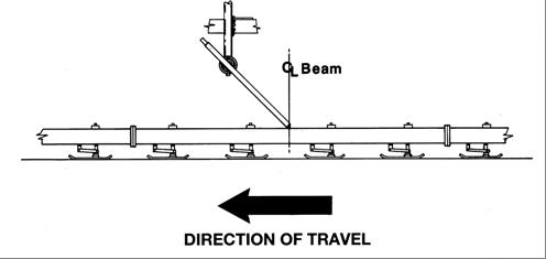
One type of reference device, termed a floating ski or beam, is a series of feet, or shoes, attached to the bottom of the floating beam. The purpose of the shoes is to allow one or more of them to pass over a high or low point in the existing surface without altering the slope of the whole beam. The grade sensor usually rides directly on the beam at its midpoint. This floating ski system averages out the variation of the existing grade over a 30 or 40 foot length. See Figure 502-6.
Grade Reference Controls
Automatic screed controls are employed to keep the elevation of the pull points on the paver at a more constant elevation relative to the grade reference being used. Deviations in the pavement surface are averaged out over the length of the grade reference device. There are four basic types of grade references that can be employed to maintain the elevation of the screed pull point: the erected string line, the mobile mat reference, 30 foot floating ski, and the joint matching shoe. Each type of reference can be used on either side of the paver, or on both sides at the same time. When a grade reference is used in conjunction with a slope control device, the grade reference sensor is typically positioned on the centerline side of the paver, with the slope controller determining the thickness of the mat on the outside edge of the pavement.
String Line
String line allows for the smoothest possible asphalt mat behind the paver screed. The elevation of the string line must be set by a survey crew and the set line must be very taut. Typically, the string is supported on metal posts at 25 foot intervals. The haul trucks and all paving personnel must keep away from the line and not disturb it in any way. Once the line is set at the proper elevation, it is imperative that the line remain untouched both before and after the paver sensor passes over.
Joint Matching Shoe
Another type of grade referencing device is the joint matching shoe. This device consists of a short 12 inch shoe or ski that is used to reference the grade of an adjacent piece of pavement or curb. This type of reference device is used only when the grade being sensed is relatively smooth. Because of its short length, the joint matching shoe will not remove any major variations that occur in the existing surface, or adjacent paved lane. See Figure 502-7.
Mobile Mat Reference System
The mobile reference system, illustrated in Figure 502-8, combines the front mounted 30 foot floating beam with a 20 foot mat reference beam. The mat reference beam is spring supported on a series of wheels that roll on the mat. It responds to and averages changes in mat elevation in the same manner as the floating beam. A superstructure that spans the screed and auger areas ties the two together and supports the grade sensor. This 55 foot overall length assembly produces a mat with an exceptionally smooth riding surface. This arrangement permits an average to be taken from the grade surface and another to be taken from the freshly laid mat. These averages are combined and measured at the grade sensor near the screed tow point. A mean average is thus obtained over the entire span. This arrangement can sense and correct any change in screed elevation.
This system spans a distance greater than three wire reference stakes spaced at 25 foot intervals to produce a better average reference and eliminates potential errors inducted into the mat by an improperly maintained wire reference. It can be configured for automatic grade and slope, or dual grade control, as shown in Figure 502-8.
Slope Control
Paving done with automatic screed controls is accomplished with a combination of grade control on one side of the paver and slope control to determine the grade on the other side of the paver. See Figure 502-6.
The slope control operates through a slope sensor that is located on a cross beam between the two side arms on the screed. One side of the paver is controlled by the grade referencing sensor and the other side is controlled by the slope controller. When slope control is used, the thickness of the mat on the side of the paver that is controlled by the slope sensor could be variable, depending upon the condition of the existing surface. The desired degree of cross slope is dialed into the slope controller. Before the automatic screed controls are engaged, the screed must be nulled before paving starts and the proper angle of attack must be set. If the automatic controls are being used, the screed operator should not try to change the screed manually by turning the thickness control crank.
Rollers
Rollers are used to compact the mixture to the required density. The Contractor will use several types of rollers and each type is used for different purposes. Three types of self-propelled rollers are currently being used: static steel wheel, pneumatic tire rollers and vibratory rollers. Fuel oil is not permitted for use on tapered joint rollers and mobile mat reference wheels.
Static
Static steel wheel rollers normally range in weight from 3 to 6 tons and have compression drums or rolls that vary in diameter from 30 to more than 60 inches. The gross weight of the roller can be altered by adding ballast water to the roller drums.
Vibratory
Vibratory rollers come in a variety of configurations. Double-drum vibratory rollers come in single-articulated-frame and double-articulated-frame models. These vibratory rollers can be operated in any one of three modes: static, with one drum vibrating and one drum static, and with both drums vibrating. For relatively thin layers of mix, generally less than 1-1/2 inch, the vibratory roller should typically be operated in the static mode. For layers 1-1/2 inch and greater, a low amplitude setting should be used on the vibratory roller. As the layer thickness increases, it may help to increase the amplitude applied to the mix as recommended by the manufacturer.
Pneumatic
Pneumatic tire rollers are required for initial compaction on all base and some leveling courses to knead the material into all cracks and depressions for better density. This type roller’s compactive effort is a function of the wheel load, the tire pressure, the tire design and the depth of penetration of the tires into the mix. All the tires should be the same size, ply and tire pressure. The tire pressure used depends, in part, upon the number of plies used in the tires. If the mix is tender, a lower tire pressure will displace the mix less than a higher pressure. For a stiff mix, a higher tire pressure should be used. It is very important that proper air pressure be maintained in all tires. This type of roller must be equipped with a skirt around the bottom of the roller and within 3 inches of the new surface. This skirt will help keep the tires hot by holding the heat from the mix under the roller. The tire surface must be kept hot to reduce the pick up of fines from the mixture being compacted. Rollers can also be a combination of both pneumatic and steel wheel.
Hand Tools
Adequate hand tools, and proper equipment for cleaning and heating them, should be available for the paving operation. These tools include rakes, shovels, lutes, 10 foot straightedge, carpenter’s level and blocks and shims for supporting the screed of the paver when beginning operations at a butt joint. Not all of these tools are necessarily used on every project, or every day of a particular job. Rakes, shovels and lutes are frequently used by personnel around the paver. While the paver is operating, laborers may work, or rework, a portion of the mix to fit the paving around objects and to fill in areas that the paver does not pave adequately, or cannot reach. Non-biodegradable agents that dissolve the HMA mixture, such as fuel oil, shall not be used at the paving site.
Surface Preperation
Aggregate Base
The ride quality of the surface depends, to a great degree, upon the conditioning and preparation of the aggregate surface. The aggregate base course must meet all the requirements for moisture content, density and smoothness. The aggregate base must provide a firm foundation before paving commences. If distortion of the base course occurs during the paving operation, the mixture placement should be stopped until the condition of the base course is corrected. If the aggregate surface is left exposed to the weather, either allowed to dry out or become saturated by rain, sufficient tests must be made immediately prior to placing the mixture to ensure that density requirements are met. Raveled, dried-out surfaces must be re-compacted and restored to the proper cross section. Saturated areas must be allowed to dry prior to placing mixture. The aggregate base must be rolled after final trimming in order to pack down any loose gravel and minor dips caused by the trimmer.
Cold-Milled Surface
The proposal and plans should be reviewed to see if the cold-milling will be for profiling, or for a specified depth. Profiling is used to establish a new cross section in the existing pavement. Milling can be accomplished in any width necessary; however, the width is typically 6.25 feet. Equipped with automatic grade and slope controls, the milling machine is capable of producing a level surface in one pass over the existing pavement. A surface that has been milled typically is very dusty and dirty. Once the pavement has dried, multiple passes of a mechanical broom are needed to remove all the residual grit from the milled surface. Care should be exercised to keep dust to a minimum. Any dust and dirt left on the milled surface will greatly affect the bond between that course and the new overlay. When cold-milling by the ton is a pay item, a weigh person will be needed. Cold-milling machines may be used to do the work involved in the pay item of removing HMA surface by the square foot (square meter).
Old HMA Pavement
Before overlaying an old HMA pavement, it should be inspected. The degree of preparation depends upon the condition of the existing surface. Slick, highly polished surfaces, potholes, old patches, cracks and joints may require repairs. At a minimum, the failed areas should be removed and replaced, the potholes properly patched, the cracks cleaned out and the ruts filled, or preferably removed by cold-milling. Proper subsurface drainage should be installed as necessary. Old patches that show signs of instability, areas with excess asphalt, or excess crack filler, and areas with loose material should be removed and repaired.
At a minimum, all repairs shown on the plans shall be completed.
The inspector should mark areas that will require wedging, which will usually occur when the existing pavement has depressions of 1 inch or more. Unless otherwise noted, the patching and wedging work is done with the mixture that will be used for the leveling course. The top course mixture can be used for wedging when the thickness is less than 2 inches. All horizontal and vertical surfaces that will be in contact with the new HMA mixture must be thoroughly cleaned. This can be accomplished by using a rotary broom, flushing with water, and other methods that may be required to remove clay and dirt. Vegetation and debris should be removed from joints and cracks. Cleaning of the roadway surface may be a pay item.
Old Rigid Pavement
Before overlaying the old pavement, it should be inspected. Any severely distressed areas in the old rigid pavement surface should be cut out, removed and replaced using full depth repairs with PCC, or hot mix asphalt. Any severely spalled areas at joints should be repaired using partial-depth repair methods. Rocking slabs must be stabilized. Joints that are poorly sealed should have the old seal material removed and the joints cleaned. Some pavements may be disintegrated so badly that the fragments may have to be removed. Pavement sags and rough areas may require a wedging course. The inspector should check the entire pavement surface to ensure that all corrections are made before resurfacing work begins. The final step before the bond coat is applied is to thoroughly clean the existing surface by brooming and/or other methods; all vegetation and debris must be removed from pavement joints and cracks.
Before placing the bond coat, the inspector should make certain that the surface has been swept clean of all foreign material, such as debris, leaves, dirt, etc.
Adjusting Drainage Structures
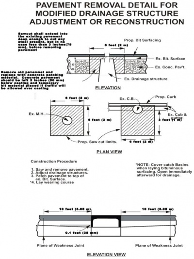
One of the greatest contributors to a poor ride on an urban project is the improper adjustment of manholes. Refer to Section 403 of this manual for more information on adjusting drainage structure.
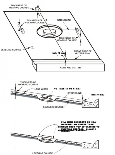
To make a proper adjustment, the inspector should string line along the roadway after the leveling course has been placed, 15 feet either side of the structure in a longitudinal direction and in a transverse direction from the centerline to the edge of pavement, or curb line. The top of the cover should be set 1/8 inch lower than the string line, adjusted to the elevation of the planned overlay. Care must be taken to adjust the top of the cover to the slope of the planned finished roadway.
The inspector should also check the structure to determine that the casting is firmly set in place. The adjacent pavement, curb, or curb and gutter, shall be replaced to the original elevation, condition and type of construction, unless otherwise provided. Refer to Figure 502-9. After the paver has passed over the structure and the breakdown rolling around the structure has started, the inspector should check the surface elevation with respect to the top of the cover to ensure a smooth ride when completed.
Hand raking and shaping around the cover must be completed before the material cools. It may be necessary to compact these areas by the hand tamper method. Structures located in the roadway should have the top of the cover flush with the wearing surface when the final compaction is completed. On structures in the curb line out of the traveled roadway, the top of the cover should be 3/8 inch (8 mm) below the wearing surface after final compaction is completed.
Improper adjustments of catch basins can create drainage problems, which will lead to early deterioration of the roadway. Adjust catch basins after the leveling course has been placed. After the paver placing the top course has passed over the structure and the hand raking and shaping have been completed, it may be necessary to compact this area by the hand tamper method. Refer to Figure 502-10.
Wedging
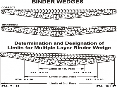
Some old surfaces may need to be leveled or smoothed before the new surface is placed. This requires a HMA layer of varying thickness to be placed and is referred to as wedging. If the wedging course is 3 inches or less, the inspector should string line the area to be wedged to determine the limits of wedging. If the wedging is greater than 3 inches, two courses of HMA mixture may be required. The thickness of each course generally should not exceed 3 inches. This process is typically used for superelevation corrections, placing a wedging course so that the leveling and top courses can be placed at a uniform thickness. Figure 502-11 illustrates the wedging process.
Bond Coat
The bond coat, also called the tack coat, consists of an asphaltic emulsion applied to an existing surface to promote adhesion between the old surface and the new asphalt overlay. If a good bond is not formed between the existing surface and the new overlay, a slippage, or sliding-type, failure can easily occur. All existing pavements, including newly-constructed HMA surfaces, which are to be surfaced with HMA, will receive a bond coat application.
The bond coat material must be applied with an approved distributor with a uniform spray. See Figure 502-12. All nozzles on the distributor should be open and functioning. All nozzles should be turned at the same angle to the spray bar: approximately 30 degrees, depending upon the manufacturer’s recommendations. In addition, the spray bar should be set at the proper height above the pavement surface to provide for a double or triple lap of the liquid asphalt materials. The bond coat material should be heated to the proper temperature so that it is fluid enough to be sprayed from the nozzles.
A bond coat is an application of an asphaltic emulsion to an existing surface as a bond or tack coat ensuring adhesion with the overlying surface and preventing displacement ahead of the roller.
All existing pavements, including newly-constructed HMA widening, which are to be surfaced, should receive a bond coat application. Bond coat material must be applied with an approved distributor with a uniform spray. The existing surface texture will determine the rate of application up to the maximum rate of 0.10 gallons/square yards. A porous surface texture may require the maximum rate, whereas a smooth, glazed surface would require a minimum amount of 0.05 gallons/square yards. This minimum rate should also be used between courses as a tack coat.
Before the application of bond coat, the surface must be dry and free of sand, gravel and dust. Bridge railings and piers, curb and gutter pans, and guardrails must be protected from the spray of bond coat by the use of shields. Plan the width of application to ensure having bond coat under the matching longitudinal joint. Avoid spraying adjacent completed surfaces that will remain exposed. The three essential requirements of a bond coat are:
- It must be thin.
- It must be uniform.
- It must be cured before surfacing.
Excess bond coat may create a slip plane between courses, bleed into the overlaying course and cause flushing. All traffic must be kept off of the bond coat until it is cured. Bond coats may be considered cured when your shoes tend to stick without picking up material when walking over it.
Whenever the temperature of the previously placed mats falls below 170°F prior to placement of the adjacent mat, or when placing base mix and the air temperature is below 50°F, the vertical edges of the initial mat shall be coated with HMA bond coat material before the mixture is placed in the adjacent section.
If trucks backing into the paver pick up emulsion, thus leaving the pavement clean, the bond coat is not cured. After curing, only traffic essential in the work should be allowed on the bond coat. The work should be planned so the bond coat is not applied too far in advance of the paving operation. Breakdowns and bad weather can create problems with large areas of bond coat that are left unsurfaced. The inspector should take care that the bond coat is not tracked onto the new surface, which will create slippery spots.
The bond coat material shall be applied ahead of the paving operation for a distance of at least 1500 feet, depending upon traffic conditions, as determined by the Engineer. The surfacing or construction traffic shall not be allowed on the existing pavement until the bond coat has cured. Only enough bond coat should be applied that can be covered the same day.
The uniform application of the emulsion is a function of the asphalt distributor and the skill of the operator. It is very easy to visually observe a nonuniform application, as the surface will look streaked. Things that can cause a nonuniform application are, improper temperature, improper pump speed, sprayer bar height improperly set, spray nozzles clogged, or the nozzle overlap pattern is improperly adjusted. When the inspector sees an improper bond coat application, the operation should be stopped. The Contractor would then correct the problem and show that a uniform application can be made before being allowed to continue paving on the project.
Placing HMA Mixture
It is the Contractor’s responsibility to uniformly place the HMA mixture to the specified grade and thickness. It is the MDOT inspector’s responsibility to ensure that the Contractor is providing a specification product.
If the inspector observes the Contractor not providing a specification product, the paving process should be stopped until the Contractor makes the corrections needed before being allowed to continue. All HMA lifts shall be placed, compacted, and allowed to cool to at least 130°F, or cool enough to support construction equipment without visible distortion or distress of the mat prior to placing any subsequent HMA layers.
Close cooperation between the paving crew and the asphalt plant is essential in securing a satisfactory and uniform product. A fast means of communication should be established between the plant and the paving crew so that any changes to the mixture can be promptly communicated. Mixture temperature should be checked regularly when the mix arrives on the project and recorded on the load tickets.
Placement Temperature
It is the Contractor’s responsibility to ensure that the mixture temperature is adequate for placement and compaction; however, if the inspector observes mixture that is either too cold or too hot, the problem should be pointed out to the Contractor and the Engineer.
- Too Hot: Blue smoke rising from the mix usually indicates an overheated truckload. The temperature should be checked immediately. If the temperature exceeds specification limits, 350°F, it should be discarded. If it exceeds optimum placement temperature, but does not exceed the specification limit, the truckload is usually not discarded, but immediate steps should be taken to correct the condition.
- Too Cold: A generally stiff appearance, or improper coating of the larger aggregate particles, indicates a cold mixture. Again, the temperature should be checked immediately. If it is below the specification limit, 250°F, it should be discarded. If it is within the specification limit, but below optimum placing temperature, steps should be taken immediately to correct the situation by contacting the plant.
- Excess Moisture. Steam rising from the mix as it is dumped into the hopper of the spreader indicates moisture in the mix. It may be bubbling or popping as if it were boiling. The mix may also foam so that it appears to have too much asphalt.
Texture
As the first load of mixture is being spread, the texture of the unrolled surface should be checked to determine uniformity. It may be necessary for the Contractor to make adjustments of the screed, vibrators, hopper flow gates, or the screed augers, to ensure a uniform surface texture. These adjustments should be completed within the first two loads placed. Refer to Figure 502-13 for some typical mat appearances.
Nonuniform mixing shows up as spots of lean, brown, and dull appearing material within areas of rich and shiny appearance. A result of specified mix contaminated with inferior performing, non-specification mix.
Yield
The inspector should check the placement yield occasionally. The first yield check should be made as soon as the Contractor has completed all paver adjustments. This check is done by roughly measuring the area covered by one truckload; the tonnage placed is known from the load ticket. Dividing the tonnage placed, by the area covered, will give the yield. To convert the yield to mat thickness, the following will be helpful: 110 pounds/square yard = 1 inch of thickness. If this yield is found to be high or low from that specified on the plans, a slight adjustment of the thickness controls should be made and the yield rechecked. Once the proper yield has been obtained, only periodic checks will be required each day.
Example:
Specification Requirement = 165 pounds/square yards
Load Ticket = 247923 pounds
Area Covered:
1000 feet x 11 feet / 9 = 1467 square yards Then: yield = 247923 lbs / 1467 yd2 = 169 lbs/yd2
Segregation
Another texture problem that may be observed is caused by material segregation. If segregation is observed, the paving operation should be stopped until the problem is corrected. The pattern of segregation can normally identify the cause of the segregation. Figure 502-14 shows some typical surface patterns and the causes.
Other surface blemishes are caused by the truck backing into the paver, the screed settling when the paver stops and when the paver operator empties the hopper wings into an empty hopper. A diagnostic guide is included here to help in identifying the cause and fix for a range of segregation problems.
Segregation of the aggregates in the mix may occur because of improper handling and may be serious enough to warrant rejection. Loads that have become contaminated because of spilled gasoline, kerosene, oil and the like, should not be used in the roadway.
|
| |
|---|---|
|
|
|
|
| |
|
|
|
|
|
|
|
|
|
|
|
|
|
|
|
|
|
|
|
|
|
|
|
|
|
|
|
|
|
|
|
|
|
|
| |
|
|
|
|
| |
|
|
|
|
|
|
|
|
|
|
|
|
|
| |
|
|
|
|
| |
|
|
|
|
|
|
|
|
|
|
|
|
|
| |
|
|
|
|
|
|
|
|
|
|
|
|
|
|
|
Joints
Attention needs to be directed toward joints more than any other phase of HMA construction. The subject of joints includes longitudinal joints and transverse joints, as well as the matched joint between an asphalt surface and a concrete pavement, or gutter pan. Refer to Figure 502-15 for details of joint construction.
Transverse Joint
The transverse joint in all courses must be carefully constructed and thoroughly compacted to provide a smooth riding surface. When the paving operation is discontinued, a transverse joint must be constructed. Although there are several ways to construct this joint, the most common is the ramp joint. This method uses paper, canvas or burlap as the separator, making it easier to remove the mix when the paving operation starts again. If the end of the lane is to be left open overnight, a ramp joint should be used. The length of temporary taper shall be 5 feet for each inch of mat thickness.
Longitudinal Joint
One of the most important considerations in making a longitudinal joint is keeping the paver on a straight line of travel. When constructing the first lane, a string line should be employed to guide the paver operator to establish a uniform edge. The lane edge should not vary more than 1 inch in 3 feet from the established alignment. The completed centerline joint should be uniform, closed and flush with adjacent lanes.
Tapered Joint
The use of a tapered, overlapping longitudinal joint eliminates the requirement that all lanes be resurfaced to within one truckload of the same point of ending. The tapered longitudinal joint shall be constructed by tapering the HMA mat; the taper shall have a 1 to 12 rise and the taper shall extend beyond the normal lane width. A notch of up to 1 inch shall be placed at the top of the taper when placing HMA. The taper shall be constructed by the use of an approved strike off device attached to the screed that will provide a uniform slope and will not restrict the main screed. Bond coat shall be applied to the taper before the adjacent lane is placed. Compaction of the taper section will be required as near to final density as possible. The paver screed will be equipped with a special template strike-off and a small weighted roller for construction and compaction of this joint.
Butt Joint
When butt joints are called for on the plans or in the proposal, construction should be as follows. Material from the existing surface is milled out to a depth as shown on the plans, or equal to the top course, across the entire width of the joint and to a length of 35 feet minimum. This should be checked using a straightedge or string line. If the depth exceeds the plan thickness by 2 inches, the Contractor must fill in the butt joint to the required thickness. Care should be taken to neatly construct the joint at a right angle to the centerline of the roadway. The joint is swept clean of all loose material and given a bond coat.
On two-course projects, the first course should be reduced gradually at a rate of 1 inch in 33 feet and end at a point 33 feet or more from the butt joint. The top course will then be placed at a uniform rate.
Echelon Paving
If two pavers running in echelon are used, the construction of the joint is similar to the building of a joint against a cold compacted pavement. However, the amount of overlap between the first and second lanes is very important. The distance the screed of the trailing paver should extend over the uncompacted mat behind the first paver should be limited to no more than 1 inch. The screed of the second paver must be set at the same level as the screed of the first paver; this will prevent the screed of the second paver from dragging on the mix placed by the first paver. No raking of the joint is needed. The rollers behind the first paver should stay 1 foot away from the free edge toward the second paver. Once the mix from the second paver is placed against the uncompacted edge, the rollers behind the second paver will densify the joint area.
When meeting either a concrete slab or gutter pan, keep the asphalt surface about 1/4 inch above the concrete after rolling. Be extremely careful when an asphalt surface is being placed on an aggregate base adjoining a slab or curb. Experience has shown that these sections generally settle after a short period of time.
Feathered Joint
When a feathered joint is required, it should be constructed as follows. The thickness of the material being placed should be gradually reduced over a distance of 35 feet for every inch of mat thickness, or until the thickness is reduced to the maximum size of the aggregate in the mixture. Stop the paver at this point, remove it from the roadway and remove any excess HMA material from the roadway. Trim the joint at right angles to the roadway centerline. The last meter of the HMA material should be raked and all the large stones removed, leaving the fine material. Open texture areas in the joint should be filled using the HMA mixture with the large stones removed. Once this has been done, complete the rolling of the joint.
Compaction
Compaction is the single most important factor that affects the ultimate performance of a hot mix asphalt pavement. Adequate compaction of the mix increases the pavement life, decreases permanent deformation, reduces oxidation or aging of the asphalt binder, decreases moisture damage, increases strength and stability and decreases low temperature cracking. An asphalt mix that has all the desirable mix design characteristics will perform poorly, if not compacted to the proper density.
It is the Contractor’s responsibility to obtain the proper pavement density. Most mixtures will compact quite readily if spread uniformly and rolled at a temperature that assures proper asphalt binder viscosity. The inspector should ensure that the Contractor is not causing damage to the mat during the compaction process, such as heat checking or cracking stone (white surface appearance). The finished mat should be smooth and free of blemishes. The number of rollers needed and the number of passes each roller needs to make will be based upon the mixture temperature and the rate at which the mixture cools.
The primary compaction variables that can be controlled during the rolling process are: number of rollers, type of rollers, roller speed, number of roller passes and roller pattern. For vibratory rollers, the following can be controlled by the operator: vibration frequency, vibration amplitude and direction of travel, when frequency and amplitude are engaged according to the manufacturer’s recommendations. Each of these factors has an effect on the level of density achieved under the compactive effort applied to the mat.
Roller Speed
The faster a roller passes over a point on the asphalt surface, the less time the weight of the roller has to work on that point; this means that less compactive effort is applied to the mixture. The roller speed selected is dependent upon a combination of factors: productivity, layer thickness and the position of the roller in the compaction process.
Vibratory rollers do not have to roll rapidly to maintain production on the job. Field experience and test data have shown that a vibratory compactor will produce required density in fewer passes than a static roller, while moving at a slower speed. Depending on the material and job conditions, this can be quite dramatic.
The fast rolling movements by some static roller operators may produce a good looking surface appearance, but density may suffer. The good looking surface texture can lull the operator into a false sense of security.
A vibratory compactor should never exceed a rolling speed that will provide less than one impact of the drum per inch of travel. Generally speaking, this means that vibratory rollers normally operate in the 2 to 3 mph range. To exceed this one impact or more per inch of travel may produce small ripples in the mat when laying HMA. Obviously the higher the frequency, the faster the vibratory compactor may roll. There are, of course, limits to this. The important part to remember is that although it rolls slower than a static roller, the vibratory machine can usually economically reach specified density with fewer passes. Slow and steady is the key to good vibratory compaction procedures.
Easy method to calculate roller speeds for proper “Impact Spacing”
Rolling Speed (Impacts per foot)
VPM / Impacts per foot = feet per minute
2500 / 10 = 250 fpm
2500 / 12 = 208 fpm
2500 / 14 = 179 fpm
Speed - fpm to mph
fpm x 0.01136 = fpm / 88 = mph
208 fpm x 0.01136 = 208 fpm / 88 = 23.36 mph
Number of Passes
Roller passes must be distributed uniformly over the width and length of the area being compacted. All too often, the center of the lane receives adequate coverage, while the edges receive considerably less compactive effort. The uniformity of the roller passes is just as important as the number of passes.
The rolling zone is the distance behind the paver where the breakdown roller operates. Compaction must be achieved while the stiffness of the mix is low enough to allow for reorientation of the aggregate particles under the action of the rollers. A rule of thumb is that the proper level of air voids should be obtained before the mixture cools to a temperature of 176°F. To reach the required density, the quickest initial compaction should occur directly behind the lay down machine. The rolling zone should be kept as short as possible.
Pattern
For each roller employed on a project, the mat width should be divided by the width of the compaction roller to determine the number of passes needed to cover the entire width being paved. A pass is defined as one trip of the roller in one direction over any one spot. Once it is determined how many passes are needed to achieve compaction at any point, the roller pattern for an area will be calculated by multiplying the number of roller passes needed for compaction by the number of rollers needed to cover the width being paved. In the longitudinal direction, the rollers should not stop at the same transverse end point with each pass of the roller; the reversal points should be staggered to prevent shoving of the mix.
A slight change in direction, or curl, is beneficial at each reversal spot to further reduce the tendency of the mix to shove under the compactor and to eliminate the possibility of a bump at the point where the roller reversal occurs. The roller should not sit and wait on the hot mat. Long delays, caused by the lack of trucks, or filling the roller with water, allow the roller to indent the new mat. It is generally impossible to roll these marks out once the mat cools.
Coring
Once the Contractor has finished the rolling operation, the inspector will identify the locations where the density cores will be taken; these locations are randomly selected both longitudinally and transversely.
Density is required across the full pavement width. If the random core location falls over a tapered joint, it should be moved to the first point that the mat is full depth. If it falls at the free edge of the pavement, the core location should be moved 2 inches in from the edge. Each individual core location is to be marked on the pavement with a 2 inch diameter paint dot which represents the center of the core. The paint dot is to be visible on the core during handling and testing.
After coring is completed, the inspector should check the layer thickness for conformance to the standard specifications. Figure 502-16 shows an example of a coring documentation form.
The MDOT procedure used for selecting random core locations is by using a random number generating computer program.
Surface Defects
Surface defects are problems that occur in the asphalt mixture during, or soon after, the lay down and compaction process. These defects can be divided into two primary categories: equipment related and mixture related. At the end of this section there is a troubleshooting guide to help in assessing possible causes and fixes for surface defects.
Waves
The surface can have two types of waves: long waves and short waves. Long waves may correspond to the distance between truckloads and may be associated with the reversal points of the rollers. Long and short waves can be caused by a fluctuating head of material in front of the screed. Short waves can be caused by a screed in poor mechanical condition, such as too much play in the screed control connections. Very short waves, or a washboard effect, can be caused by improper operation of the vibratory roller.
Tearing
There are three types of mat tearing, or pulling, of the asphalt mix, and each is described by the location of the tear: in the center of the lane, at the outside edges of the lane, or full width. These tears are usually caused by improper paver condition, or operation, by cold mix, and by attempting to lay a mat too thin compared to aggregate size.
Screed Marks
Nonuniform mat texture can appear in the mat both transversely and longitudinally. This nonuniform texture can be caused by many factors: screed extensions not level with each other, running the hopper empty between trucks, unevenly worn screeds, cold mix, or improperly emptying the paver wings. Transverse screed marks are transverse indentations in the mat, which may occur when the paver stops between truckloads. This is caused by an improperly adjusted screed angle of attack.
Checking
Checking is short transverse cracks, usually 1 inch to 4 inches in length and 1 inch to 3 inches apart. Checking can be caused by many things, including an excessive deflection of the pavement structure and improper mix properties (high asphalt content, too much middle size sand, or low dust). If the surface of the mat is cooling much faster than the mixture under it, the surface will check as the hot mix is compacted.
This will happen on windy days and when the mat thickness is thin, normally the wearing course.
Fat Spots
Fat spots are isolated areas where the asphalt cement has come to the surface; these spots can occur very erratically. Bleeding (flushing) occurs when the asphalt cement comes to the surface under traffic. Fat spots can be caused by high moisture in the mixture; if the mixture is very hot, asphalt could run down to the bottom of the truck during transport and cause fat spots when dumped into the paver. Bleeding can be caused by too much asphalt cement in the mixture, or by allowing traffic onto the paved surface before the surface has cooled sufficiently.
Surface Tolerance
The importance of staying within the surface tolerance for smoothness cannot be overemphasized.
Irregularities in the lower courses can usually be corrected by removing or adding material. In the surface course, the entire affected area should be removed promptly and sufficient new material placed to form a true and even surface. If the required smoothness is obtained in the first course, the subsequent courses can usually be placed uniformly by simply setting the paver for the thickness desired.
Ride Quality
|
| |
|---|---|
|
|
Trucks backing into the paver. |
|
|
Emptying the paver wings when the hopper is empty. |
|
|
Placing segregated mixtures. |
|
|
Stopping the paver and allowing the screed to settle into the mat. |
|
|
Placing the mat too thin based upon the aggregate size. |
|
|
Improper rolling procedures. |
|
|
Improper base preparation. |
|
|
Transverse joints not being properly constructed. |
|
|
Malfunction of the paver automation. |
Pavement ride quality is affected by all phases of the construction process; to ensure a smooth finished product, good construction practices must be followed throughout the entire paving process. Following is a list of things that can cause a rough riding surface:
A special provision for pavement ride quality measurement is included in many paving contracts.
Paving Inspector's Checklist
Things to look for during the paving operation include:
|
| |
|---|---|
|
|
The trucks should be loaded in multiple drops. |
|
|
The trucks should have tarpaulins. |
|
|
If required, the truck bed should be insulated. |
|
|
Trucks should stop short of the paver and be picked up by the paver. |
|
|
The dump bed should not hit the paver when dumped. |
|
|
There should be enough trucks to provide a continuous flow of mix to the paver. |
|
| |
|---|---|
|
|
Ensure existing surface failures are repaired properly. |
|
|
Cracks should be cleaned. |
|
|
Joints in PCC pavement should be cleaned. |
|
|
Rough, uneven surfaces should be leveled. |
|
|
Ensure the surface is cleaned of all dust, dirt and other debris. |
|
|
Ensure the bond coat has been applied uniformly at the proper yield. |
|
|
Ensure the bond coat has broken before paving starts. |
|
| |
|---|---|
|
|
If automation is required, ensure it’s on and working. |
|
|
The operator should not make manual changes while automation is working. |
|
|
The screed should be hot. |
|
|
The screed extensions should be level with the main screed. |
|
|
The augers must be extended if the screed is extended. |
|
|
Never empty the paver hopper while paving. |
|
|
Keep the level of mix in the hopper above the flow gates. |
|
|
Try to keep the paver moving at a constant speed. |
|
|
When the paver stops, do it as fast as possible. |
|
|
When the paver starts, go to paving speed as fast as possible. |
|
|
Ensure the paver speed matches mixture delivery. |
|
|
Keep the level of mix at the augers as uniform as possible. |
|
|
Ensure the flow gates are set properly. |
|
| |
|---|---|
|
|
Ensure sufficient compaction capacity is available. |
|
|
Ensure mixture temperature is high enough for proper compaction. |
|
|
The pneumatic roller must be skirted. |
|
|
The breakdown roller should be as close to the paver as possible. |
|
|
The roller pattern should be set up as soon as paving starts. |
|
|
Check the mixture thickness, or yield, within the first three truckloads. |
|
|
The roller’s vibratory frequency should match its travel speed. |
|
|
All roller marks should be removed by the finish roller. |
Mat Troubleshooting Guide
|
|
|
|---|---|
|
| |
|
|
|
|
|
|
|
|
|
|
| |
|
|
|
|
|
|
|
|
|
|
| |
|
|
|
|
|
|
|
| |
|---|---|
|
|
|
|
|
|
|
|
|
|
|
|
|
|
|
|
| |
|
|
|
|
| |
|
|
|
|
|
|
|
|
|
|
| |
|
|
|
|
|
|
|
|
|
|
|
|
|
|
|
|
| |
|
|
|
|
|
|
|
|
|
|
|
|
|
|
|
|
|
|
|
|
|
|
| |
|
|
|
|
| |
|
|
|
|
| |
|---|---|
|
|
|
|
|
|
|
|
|
|
| |
|
|
|
|
|
|
|
|
|
|
|
|
|
|
|
|
|
|
|
|
|
|
| |
|
|
|
|
|
|
|
|
|
|
|
|
|
| |
|
|
|
|
|
|
|
|
|
|
|
|
|
|
|
|
| |
|
|
|
|
|
|
|
|
|
|
|
|
|
|
|
|
| |
|---|---|
|
|
|
|
|
|
|
|
|
|
| |
|
|
|
|
|
|
|
|
|
|
|
|
|
|
|
Temporary Patching with HMA Mixture
- The HMA mixture used for patching should be the top course mixture called for on the plans, or in the proposal. However, if the project does not call for HMA mixtures, or the patching is in advance of the paving operation, any mixture readily available and approved by the Engineer can be used. The inspector should contact the Region HMA inspector for guidance.
- Before placing any HMA patch, the area to be patched must be cleaned and a bond coat applied. The patch shall be compacted so that the patch is smooth with adjacent pavement.
MEASUREMENT AND PAYMENT
Payment
The amount bid for HMA may be adjusted. These adjustments are based upon the mixture acceptance test results and the pavement in-place density, and are explained in the contract special provisions.
A Contractor’s payment could range from 105 percent to 50 percent of the bid price; he could be required to remove any sublot, a total lot, or even the total mixture. It is also possible to require the Contractor to remove a sublot of leveling course mixture that has already had the top course mixture placed upon it.
Documentation
It is required that accurate and complete records be kept for all paving projects. This is true for both the Project Engineer and his staff and for the Contractor’s general superintendent, plant and paving superintendents and all foremen. Trying to reconstruct events at a later time without written notes and complete test data is usually frustrating and often results in conflicting opinions as to exactly what happened. One procedure should constantly be followed: if in doubt about whether the information is important or beneficial, write it down. The results of all daily and periodic tests conducted at the asphalt plant must be recorded on the appropriate MDOT form.
|
| |
|---|---|
|
|
|
|
|
Testing Of Bituminous Mixtures (Vacuum Worksheet) |
|
|
Daily Report of HMA Plant Inspection |
|
|
Report of Quality Assurance Testing |
|
|
Daily Report of Contractor's Quality Control Tests |
|
|
Testing Of Bituminous Mixtures (Centrifuge Worksheet) |
|
|
Verification Testing of HMA Mixtures Marshall Density and Percent Air Voids |
|
|
Report of Compacted Bituminous Mixture Core Density & Percent Compaction |
|
|
Verification Testing Of HMA Mixtures Theoretical Maximum Density (TMD) |
|
|
Pycnometer Calibration Worksheet |
|
|
Testing of Bituminous Mixtures Ignition Furnace Worksheet |
|
|
Sample Identification |
Information on what occurred on the paving operation must be recorded on the inspector’s daily report and should include:
|
| |
|---|---|
|
|
Was the bond coat applied properly? |
|
|
What was the temperature of the mix delivered? |
|
|
Did the paver have to stop and wait for trucks? |
|
|
What number and type of rollers were used? |
|
|
Was any surface distress noted? |
This will allow for a better understanding later if deficiencies develop in the performance of the final product. This information must be detailed and complete. If a conversation is held with other project personnel concerning project activity, the date and location of the conversation should be recorded. The names and titles of any people involved in the discussion should be written down, as well as the topics discussed. The outcome of each conversation must be recorded; who told whom to do what, and what was the reply?
Note
The amount bid for HMA may be adjusted. These adjustments are based upon the mixture acceptance test results and the pavement in-place density, and are explained in the contract special provisions.
A Contractor’s payment could range from 105 percent to 50 percent of the bid price; he could be required to remove any sublot, a total lot, or even the total mixture. It is also possible to require the Contractor to remove a sublot of leveling course mixture that has already had the top course mixture placed upon it.
MDOT Standard Practice for Random Sampling of HMA Materials
Sampling In-Place Paving Material
Determine the length of one pavement representing a sublot of material, the width of the pavement and the number of samples, (n), needed for each sublot. Following the example below and accompanying Table 1, pick n numbers corresponding to the length of pavement, followed by picking n numbers for width determination.
EXAMPLE
A sublot is defined as 1 mile for this example of in-place 12 foot wide pavement. A specified number of samples are to be taken from each sublot. Since there are 5280 feet in the sublot, pick two numbers using the random number generating calculator, which are then multiplied by 5280. In this instance, the two numbers chosen were: 0.376 and 0.529, for length and transverse offset.
Thus, the samples will be taken at 1985 and 6.3 feet from the beginning of the pavement.
Therefore, the first sample should be taken 1985 feet from the beginning of the pavement and 6.3 feet from the designated (right or left) edge of the pavement.
This process will be repeated for additional samples.
