705 - Foundation Piling
GENERAL
Foundation piles are usually steel H sections or cast-in-place (CIP) concrete in steel shells.
Fluted shells are usually an allowable alternate but rarely used. Occasionally the plans specify treated timber piles.
MATERIALS
Bearing Capacity
Dynamic Formula
Bearing capacity of foundation piling will be determined either by the static or dynamic formula. The dynamic formula is generally used.
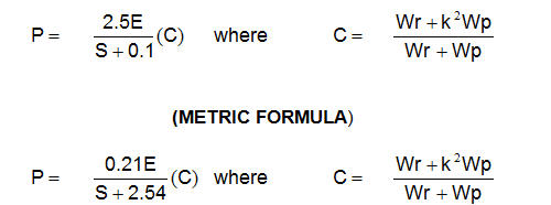
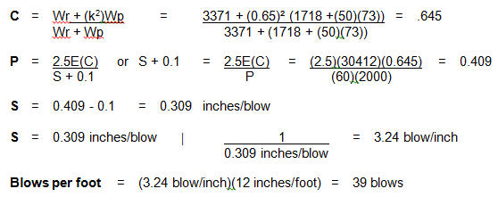
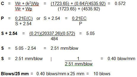
Using the dynamic formula, test piles are driven with pile lengths determined from these results. When using the dynamic formula first solve for the coefficient (C) and then solve for (S) using the following equations. A worked example is included.
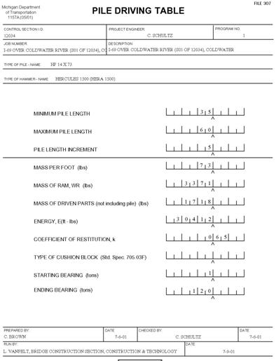
The following information is necessary so bearing charts can be made up prior to the start of work. The bearing charts are obtained by providing the Lansing Construction & Technology, Bridge Construction Section with the hammer information along with the minimum and maximum estimated pile lengths to be used. Charts can also be developed in the field using the formula.
|
|
|
|---|---|
|
|
manufacturer's maximum rated energy in foot (joules). |
|
|
weight of striking parts of the hammer (ram) in pounds (kilograms). |
|
|
weight of the parts being driven and including the anvil (if any), driving helmet, driving cap, mandrel, pile weight, etc., in pounds (kilograms). |
|
|
coefficient of restitution of the impact areas. |
|
|
bearing resistance value in pounds (kiloNewtons). |
|
|
pile set, the average penetration in inches (mm) per blow for the last 10 blows of the hammer. |
Ordering Pile Driving Charts
When the chart is needed immediately, complete Form 1157A (see Figure 705-4) on-site and phone the information in to the C&T Bridge Construction Section.
Static Formula
When the static formula is used, Design Division will compute the length necessary and the piling will be driven to the penetration shown on the plans unless practical refusal is obtained at a higher elevation.
|
|
|
|---|---|
|
|
a bearing of 1-1/2 times the required pile bearing as determined by using the dynamic formula. |
|
|
a bearing of 2 times the required pile bearing as determined by using the dynamic formula. |
Determination of Bearing Value Using Dynamic Formula
Example:
|
|
|
|
|---|---|---|
|
|
|
weight of striking parts of hammer |
|
|
|
weight of parts being driven including pile weight [(1718) + (50 ft)(73 lbs/ft)] |
|
|
|
energy of hammer |
|
|
|
coefficient of restitution for laminated Micarta blocks |
|
|
|
bearing resistance |
|
|
|
pile set, average penetration in inches/blow for the last ten hammer blows |
Metric Example:
|
|
|
|
|---|---|---|
|
|
|
weight of striking parts of hammer |
|
|
|
weight of parts being driven including pile weight |
|
|
|
energy of hammer |
|
|
|
coefficient of restitution for laminated Micarta blocks |
|
|
|
bearing resistance |
|
|
|
pile set, average penetration in mm/blow for the last ten hammer blows |
CONSTRUCTION
Equipment
Pile Hammers
Vibratory equipment may be used for sticking piles, but not for advancing piles.
Drop hammers are not permitted for driving permanent piling.
Hammers used for pile driving will be:
- single acting steam (air),
- double acting steam (air), or
- diesel-powered.
In leads which do not bind or restrain free vertical movement, and equipped with a suitable bonnet or cap which will accurately hold the pile top in correct position with reference to the ram, in order to distribute the ram blow over the entire top of the pile.
Leads
Leads used for pile driving are either swing or fixed-type.
The Contractor should be encouraged to use the fixed-type wherever possible as they do a better job of holding the pile in position.
Single Acting (Air) Hammers
The hammer is generally assumed to be developing its rated energy when it is striking the number of blows per minute as shown in the manufacturer's catalog. If a hammer will not develop its rated number of blows at bearing, the inspector should suspend driving operations. In most cases, the problem is caused by insufficient pressure at the hammer because of line losses caused by leaky connections, excessive line length, etc.
Closed-Top Type Hammer
The maximum rated energy should be used in calculating bearing only when the hammer is on the verge of floating on top of the pile. If this floating action is unattainable, the Contractor should furnish an instrument to measure the bounce chamber pressure and resulting hammer output.
Open-Type Diesel Hammer
When using an open-type diesel hammer, the manufacturer's rated energy should be used, providing the hammer appears to be functioning properly.
Construction Inspection
Prior to the start of driving and during the operation, check all of the following:
- Excavation - The excavation will be complete.
- Embankment Areas - Embankment will be completed to the bottom of substructure concrete elevation.
- Battered Piles - Proper elevation of fill or cut. Check to ensure that battered piles will clear the toe of any cofferdam sheet piling.
- Wall-type Abutments - On certain types of abutments, an error in grade could easily result in the piling being too close to or possibly outside the wall forms.
- Pile Layout - The Contractor will do the actual pile layout. The layout should then be checked by the inspector.
- Soil Borings and Blow Count Data - Prior to driving, the inspector should become familiar with the soil borings in the footing area. The problem of leaving the piling hung up on a thin, hard layer underlain by unsuitable material can be avoided.
- Embankment Areas - When specified, holes will be pre-bored to the elevation shown on the plans. The diameter of the pre-bored hole shall be equal or slightly greater than the piling diameter.
- Refusal - The specifications allow stopping at absolute refusal if minimum pile penetration has been achieved. If an underlying soft material layer exists, the region soils Engineer or representative or the C&T Lansing office should be contacted to determine if penetration is necessary, requiring extra work.
Test Piles
Will be driven prior to the regular piling so the results can be used as a guide in ordering piles and driving all the regular piling.
Will be driven to practical refusal with bearing observations taken at 1 foot (300 mm) intervals.
Pile Penetration Observations
It is important at the start of the blow count to reference the pile to some fixed object, preferably the leads, providing they are not reset during the observation period.
Reference Stake
Driving a reference stake adjacent to the pile should be avoided because clay soil has the tendency to heave and sandy soil has the tendency to consolidate.
Soil heaving and consolidating soil would raise or lower the reference stake causing erroneous penetration readings affecting the recorded bearing.
Besides the penetration readings, the inspector will simultaneously record the distance the pile point is below cutoff. This is accomplished by having the piling marked off in 1 foot (300 mm) intervals starting from the point and referencing the piling marks to a grade stake set at cutoff elevation.
Splicing
Steel piles and steel pile shells may be furnished in full length sections or the pile shells may be spliced according to the splicing method as shown on the plans or as approved by the Engineer.
Splices will be made according to subsection 707.03.D.10 b,c,d of the Standard Specifications for Construction with the welding done by a certified welder qualified in the 2G position for welding the pile in the vertical position. If the piling is spliced while lying on the ground, the welder will also be qualified in the 3G position. There is no limit to the number of splices made on any one pile.
Welded
Welded splices for piles will be made only by qualified welders using E6010, E7015, E7016 or E7018 electrodes.
CIP Concrete Piles
Shells for CIP concrete piles will be spliced using a chill ring or other type backing detail as shown on the plans.
Steel Piles
Steel piles will be spliced as shown on the plans using preformed-preassembled bent plates or flat splice plates.
Full Penetration, Butt Welded
Full penetration butt welding of piles will be performed as outlined herein, with emphasis placed on burning, alignment and welding.
Scarfing
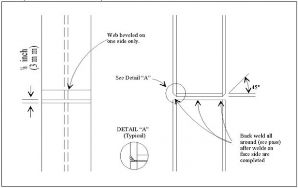
Scarfing the upper splice length of the piles preparatory to butt welding will be done by a cutting torch using a guide to assure a smoother chamber. A maximum of 1/8 inch (3 mm) land (shoulder) will be retained. If the end of the driven length of pile is damaged during the driving operation, it must be trimmed.
All splices require welding. Splicing devices which do not develop the full plan weld are not permitted.
Offhand Burning
Offhand burning will be permitted if trimming is minor. When it is necessary to cut a small section off the end of the driven pile length to square the end, burning must be done using a guide either clamped or tack welded in place. All adhering slag will be removed and the joint surfaces will be thoroughly cleaned by wire brushing before welding. A root opening of the butt joint will provide a 1/8 inch (3 mm) clear opening at the nearest point. When the 1/8 inch (3 mm) opening at the nearest point allows more than a ¼ inch (6 mm) opening at other points, correction will be made to provide the correct opening before welding. Beveling by cutting will be required for correcting openings wider than ¼ inch (6 mm).
Root Opening
The root opening may be held by two wedges before tacking. The members to be welded will be brought into correct alignment along the pile length and held rigidly by clamps or by dogging. Clamps or dogs may be removed after tack welding sufficiently to hold the member in place. Where the parts are restrained against bending due to eccentricity in alignment, an offset not exceeding 10 percent thickness of the thinner part joint, but no more than 1/8 inch (3 mm), may be permitted as a departure from the theoretical alignment. In correcting misalignment, the parts will not be drawn into a greater slope than ½ inch per foot (12 mm in 300 mm). Offset measurement will be based upon the centerline of parts unless otherwise shown on the drawing. The root pass will be a stringer bead, placed with sufficient amperage to fully penetrate through the joint. Passes will be made symmetrically and will alternate on both flanges to minimize distortion. After the face side of both flanges and web have been welded completely, a backing bead will be made on the opposite side.
MEASURMENT AND PAYMENT
PRODUCTION PILES
Recording Production Piles
Only the original length, splice lengths, final penetration bearing and cutoff lengths are recorded.
Required Bearing
Production piles are driven to the required bearing and the driving is stopped provided the pile has been driven to the minimum penetration as shown on the plans.
Overdriving
Any unnecessary production piling overdriving is to be avoided as it adds unnecessary project cost.
Equipment Changes
All piles for a given foundation unit will be driven with the same hammer operated under the same conditions with the same cushion material as used to drive test piles. Changing hammers requires additional test pile driving at the Contractor’s expense.
Variation
Piling will be driven with a variation of not more than ¼ inch per foot (20 mm/m) from vertical or the batter line shown on the plans.
Batter
The batter is checked by making a template to the shape shown on the plans. With a carpenter's level attached to the vertical side of the template, it should show when the template is held against the pile in its battered position.
Pile Position
After driving, each pile position at the cutoff elevation will be within 6 inches (150 mm) of plan position, with a minimum 9 inches (225 mm) concrete cover in all directions. Piles used as pier columns will meet the plan accuracy requirements.
Inspection
After driving CIP shell piling inspection will be done by using a mirror or light provided by the Contractor, suitable for illuminating the shell interiors. The shells will be free of bends, kinks or other deformations that would impair the completed pile strength.
Pile Tops
After driving the piling, piling tops will be immediately covered to keep out rain, sand, etc. The piling should be cut off within 1 inch (25 mm) of the specified elevation and filled with grade S1 concrete as soon as possible.
Driving
Driving within a radius of 25 feet (7.5 m) will not be permitted until the concrete has attained 75 percent of its design strength.
Concrete
Concrete should be cast in slowly so that an air pocket is not formed in the pile. An inspector should be present at all times during placement. No concrete will be placed in any pile until all piles within a 20 foot (6 m) radius have been driven and accepted.
Piles 60 feet (20 m) or more in Length
Approximately 2 cubic feet (0.05 m3) of Type R-2 mortar will be placed in the bottom of the steel shell before placing the grade S1 concrete.
Upper 1/3 Pile Shell
Concrete in the pile shell’s upper third [not to exceed 25 feet (7.5 m)], will be vibrated by an approved method.
Record-Keeping
Test Pile Records
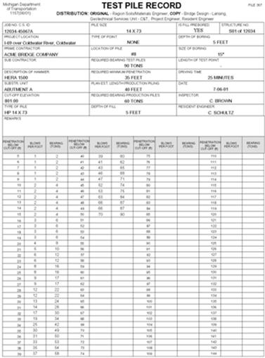
Test pile records will be kept on Form 1157.
Timber or Treated Timber Piling
Where timber or treated timber piling is called for on the plans, the Engineer will furnish the Contractor with the lengths to be ordered.
Treated timber piles (furnished) will be paid for by the length determined by the Engineer.
CIP Concrete and Steel Pile
The Contractor will be responsible for ordering pile lengths for CIP concrete and steel piling based on test pile results.
Pile Sketch
A pile sketch will be made if the pilings are not numbered on the plans or if the final driven position changes.
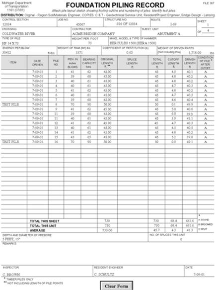
Form 1161 - Foundation Piling Record
Regular piling information is kept on this form. Measurements for driven lengths and cutoffs will be made in feet (m) and inches (mm).
The information should be recorded onto the form directly and not on separate sheets of paper that are easily misplaced. To ensure against loss, a copy of each day's driving should be made, or a permanent record can be made in a bound field book.
Note: See examples of Form 1157 - Test Pile Record and Form 1161 - Foundation Piling Record - shown in Figures 705-2 and 705-3.
