Difference between revisions of "711 - Bridge Railings"
| Line 175: | Line 175: | ||
[[Category:Construction Manual]] | [[Category:Construction Manual]] | ||
| + | [[Category: Division 7]] | ||
| + | [[Category: Section 711]] | ||
Revision as of 16:34, 12 May 2021
GENERAL
Bridge railings, along with the bridge deck overhang act to structurally withstand impacts from errant vehicles to prevent departure from the bridge. As such, the correct steel reinforcement spacing in both the railing, and the bridge deck, along with the correct placement of railing elements and connection hardware is critical to ensure crash worthiness.
Bridge railings may be constructed of steel or concrete. Although shop drawings are not necessary for bridge railings designed and constructed in accordance with department standard plans, any deviations from the standards must be approved by the Engineer, and require the submittal of shop drawings and structural calculations for review and approval. Bridge railings must be constructed in accordance with the project plans and approved shop drawings, if necessary. Contact Bridge Field Services for assistance in reviewing bridge railing shop drawing and structural calculations. The following are commonly used bridge railing types.
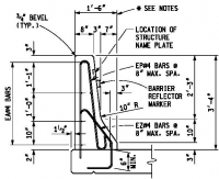
- Bridge Barrier Railing, Type 4
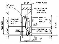
- Bridge Barrier Railing, Type 5
- Bridge Railing, 2 Tube
- Bridge Railing, 4 Tube
- Bridge Railing, Thrie Beam Retrofit (R4 Type Bridge Railing)
- Bridge Railing, Thrie Beam Retrofit (Open Parapet Type Bridge Railing)
- Bridge Railing, Aesthetic Parapet Tube
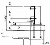
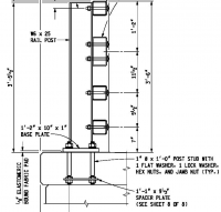
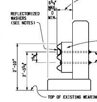
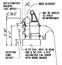
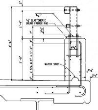
Figures 1 through 7 illustrate cross sections of the railing standard plans, though the details differ slightly depending on curb, sidewalk, aesthetic treatments, and other bridge specifics.
MATERIALS
Steel Railings
All steel bridge railing and associated hardware must be hot dip galvanized. After the railing has been galvanized it may not be punched, drilled, cut, or welded. When indicated in the contract documents the galvanized steel can also be painted. All welded post assemblies are to be blast cleaned prior to galvanizing.
CONSTRUCTION
Steel Railings
Visually inspect all bridge railing. Any deficiencies in the galvanizing or painting must be repaired. Curved sections should be free of any kinks from the fabrication or handling processes.
Ensure anchor bolts are of the correct size, type, and in the correct locations. Ensure the Contractor uses a template must be used for setting the anchor bolts. If anchor bolts are installed out of plumb, at too low of an elevation, or otherwise in the incorrect location it can be difficult and expensive to replace or repair, therefore it is imperative that they are secured in the correct location, with the appropriate length of bolt projection from the top of the nut before casting them in concrete.
Tube railing must be erected with the longitudinal seam weld facing downward to match the approved crash tested orientation. Ensure the Contractor places railing splices, and expansion sleeves as shown in the plans. Once installed tighten nuts for the anchor bolts to a snug tight condition in accordance with subsection 707.03.D.7.c of the standard specifications.
Concrete Railings
Concrete railings must be cast in accordance with section 706 of the standard specifications using smooth and tight fitting forms. Slip forming is not permitted. Prior to forming and casting concrete, ensure steel reinforcement embedded in the bridge deck protrudes into the railing as shown on the plans, and ensure all reinforcement is properly spaced.
Note angle terminations on concrete railings on skewed bridges at expansion joints and bridge approaches, and ensure proper orientation of the expansion joint rails embedded in the toe of the railing. Ensure concrete railings attached to the structure terminate at the abutment or approach slab expansion joints as shown on the plans, as to not fix sections meant for expansion.
Finished concrete shall be free of cracks, spalls, honey combing, or other defects, and exposed vertical and top surfaces shall be given a rubbed surface finish. If shown on the plans, ensure the Contractor places vertical construction joints at the required spacing
When light standards are attached to concrete railings, ensure the light standard anchor bolt assemblies and foundation reinforcement cage are properly attached to the railing rebar, and the railing forms are adjusted to accommodate larger cross section. Ensure light standard anchor bolts will extend through the top of the railing, through the base plate, and allow at least one bolt thread to extend past the nut.
Ensure handhole frame and lids are in the correct location, and properly secured to the barrier reinforcement to prevent movement or rotation during the concrete railing pour.
Bridge Railing Thrie Beam Retrofit
Holes or slots in thrie beam elements must be drilled, flame cutting is not permitted. Prior to drilling holes in existing concrete the reinforcing steel must be located by using a pachometer or other non-destructive methods, marked out, and avoided when drilling. The use of hammer drills should be avoided, as these typically cause concrete spalls upon exiting the concrete. Core drill rigs are preferred.
Nuts at thrie beam expansion section must only be finger tightened, and the first bolt-thread outside the nut must be upset with a center punch or cold chisel, to prevent loosening. Ensure bolts are fully engaged in the nuts, with at least one bolt thread extending past the nut.
Ensure the Contractor places a new structure name plate at the end of the railing on the fascia side should the thrie beam retrofit cover the existing name plate.
Reflective Markers
Ensure the Contractor removes all dirt and curing compound prior to the application of adhesive to attach the reflective marker to the barrier.
MEASUREMENT AND PAYMENT
-Reserved-
