Difference between revisions of "712 - Bridge Rehabilitation, Concrete"
| Line 331: | Line 331: | ||
Epoxy overlays, or floodcoats have been used as a preventive maintenance treatment on bridge decks in Michigan since the mid 1990’s. The early floodcoats were a mix of thin epoxy overlays and penetrating sealers, much like today, however, they were expensive, time consuming and were of questionable effectiveness in terms of longevity. Since then, many improvements in material and application have been made through employee ingenuity and industrial innovations. By educating employees on the proper use and how to identify candidates for preventive treatments, fast, effective and long lasting floodcoats may be ensured to extend the life of Michigan’s structures. | Epoxy overlays, or floodcoats have been used as a preventive maintenance treatment on bridge decks in Michigan since the mid 1990’s. The early floodcoats were a mix of thin epoxy overlays and penetrating sealers, much like today, however, they were expensive, time consuming and were of questionable effectiveness in terms of longevity. Since then, many improvements in material and application have been made through employee ingenuity and industrial innovations. By educating employees on the proper use and how to identify candidates for preventive treatments, fast, effective and long lasting floodcoats may be ensured to extend the life of Michigan’s structures. | ||
| − | '''Floodcoats''' | + | *'''Floodcoats''' |
Floodcoat is a term used to describe the flooding of an entire bridge deck with a material to seal or bridge cracks to prevent moisture intrusion. While this term used to reference a thin epoxy overlay, it is in fact an application method and not an actual preventive treatment. Other methods of sealing cracks may be used, such as; crack chasing, spraying and rolling. The floodcoat method pours material on the deck and then squeegees or brooms the material over the entire surface, essentially flooding the deck. Floodcoating is typically used with thin epoxy overlays and penetrating sealers such as healer sealers, however, the term may be applied to other materials similar in nature. | Floodcoat is a term used to describe the flooding of an entire bridge deck with a material to seal or bridge cracks to prevent moisture intrusion. While this term used to reference a thin epoxy overlay, it is in fact an application method and not an actual preventive treatment. Other methods of sealing cracks may be used, such as; crack chasing, spraying and rolling. The floodcoat method pours material on the deck and then squeegees or brooms the material over the entire surface, essentially flooding the deck. Floodcoating is typically used with thin epoxy overlays and penetrating sealers such as healer sealers, however, the term may be applied to other materials similar in nature. | ||
| Line 337: | Line 337: | ||
[[File:Fig712.5.png|600px|thumb|center|Figure 712.5 Flooding a bridge deck with an epoxy penetrating sealer (healer sealer).]] | [[File:Fig712.5.png|600px|thumb|center|Figure 712.5 Flooding a bridge deck with an epoxy penetrating sealer (healer sealer).]] | ||
| − | '''Choosing Method of Application''' | + | *'''Choosing Method of Application''' |
There are many factors to consider when choosing an application method for epoxy sealers. The primary factor is deck cracking. '''A simple rule to follow is the 2 foot rule. If the cracks are more than 2 feet apart, then crack chase each individual crack, if the cracks are less than 2 feet apart, then floodcoat the entire deck.''' | There are many factors to consider when choosing an application method for epoxy sealers. The primary factor is deck cracking. '''A simple rule to follow is the 2 foot rule. If the cracks are more than 2 feet apart, then crack chase each individual crack, if the cracks are less than 2 feet apart, then floodcoat the entire deck.''' | ||
| Line 352: | Line 352: | ||
| − | '''Thin Epoxy Overlay vs. Healer Sealer''' | + | *'''Thin Epoxy Overlay vs. Healer Sealer''' |
Thin epoxy overlays and healer sealers, though both epoxy systems, are uniquely different. They both seal the cracks in bridge decks but do so in different methods. A thin epoxy overlay “bridges” the cracks in a deck. The thin epoxy overlay acts as a sacrificial layer on the bridge that prevents moisture from entering the cracks. It is a two coat system, each coat consisting of a layer of epoxy and aggregate. The epoxy is applied approximately 1/8 inch thick and followed by a layer of small aggregate, typically chipped flint, quartz or bauxite. Because this type of system does not penetrate and only bridges the cracks, it is imperative that the preparation to the deck prior to application be done properly. The preparation involves a heavy shotblast to remove any contamination and properly profile the deck surface. The overlay must bond to the aggregate in the concrete deck. The cement mortar is not strong enough to provide a proper bond and will result in a failure of the thin epoxy overlay. By shotblasting the deck heavily the top layer of mortar is removed and the aggregate in the deck is exposed. This ensures all contamination has been removed and allows the epoxy to bind to the large aggregate, creating a strong bond and preventing delamination of the overlay. | Thin epoxy overlays and healer sealers, though both epoxy systems, are uniquely different. They both seal the cracks in bridge decks but do so in different methods. A thin epoxy overlay “bridges” the cracks in a deck. The thin epoxy overlay acts as a sacrificial layer on the bridge that prevents moisture from entering the cracks. It is a two coat system, each coat consisting of a layer of epoxy and aggregate. The epoxy is applied approximately 1/8 inch thick and followed by a layer of small aggregate, typically chipped flint, quartz or bauxite. Because this type of system does not penetrate and only bridges the cracks, it is imperative that the preparation to the deck prior to application be done properly. The preparation involves a heavy shotblast to remove any contamination and properly profile the deck surface. The overlay must bond to the aggregate in the concrete deck. The cement mortar is not strong enough to provide a proper bond and will result in a failure of the thin epoxy overlay. By shotblasting the deck heavily the top layer of mortar is removed and the aggregate in the deck is exposed. This ensures all contamination has been removed and allows the epoxy to bind to the large aggregate, creating a strong bond and preventing delamination of the overlay. | ||
Revision as of 14:55, 19 May 2014
GENERAL
Rehabilitation of bridge concrete includes deck removal, deck patching, post-installed adhesive and mechanical anchors, mechanical reinforcement splicing, rigid overlays, epoxy overlays, substructure patching, joint repair or replacement, crack sealing, crack injection, grouting, and carbon fiber wrapping. These rehabilitation techniques, or any combination of them, are used to improve the existing condition, and increase the service of the bridge. The MDOT Project Scoping Manual offers excellent guidance on the method of determining the rehabilitation techniques.
Weather Limitations
See Section 712 of the Standard Specifications for Construction for Cold and Hot Weather Limitations.
MATERIALS
-Reserved-
CONSTRUCTION
Ridgid Overlays
Rigid overlays are used in bridge rehabilitation to improve the top surface of the bridge deck which is showing signs of deterioration. Rigid overlays are a densified cementitious layer meant to waterproof and protect the existing bridge deck while improving the wearing course and ride quality of the structure. Shallow overlays are typically scoped for structures that are showing signs of deterioration of the top and bottom of the deck, yet not to the extent to warrant a deck replacement and involve removing concrete to the top of the top mat of reinforcement. Deep overlays are typically scoped for structures that have deterioration in the top of the deck with a sound underside and involve removing concrete to below the top mat of deck reinforcement. Preparation for placement of rigid overlays typically involves an initial pass with a scarifier followed by hydrodemolition to the required design depth. Typical rigid overlay materials are LMC, SFMC and Grade DM concrete.
Deck Removal and Deck Patching
Deck patching is recommended when less than 10 percent of the bridge deck area is indicative of spalling or delaminations, and is typically not shown on the plans, but rather quantified in contract pay items. Deck patching involves sounding and marking areas of concrete removal, saw cutting the boundaries, hand chipping shallow or hand chipping deep, patch preparation and placing of the new concrete. Deck patching must be conducted in accordance with section 712 of the Standard Specifications for Construction.
- Saw Cutting
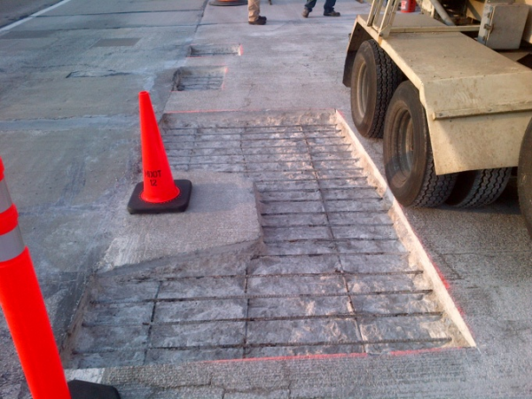
The Engineer will determine the areas to be patched in accordance with the plans. Ensure the saw cut perimeter extends to sound concrete to ensure all delaminated concrete is removed. Patches spaced at less than 1 foot must be combined into larger patches. After the locations to be patched are marked the perimeter of the patch should be saw cut to a minimum depth as shown on the plans, typically 1”. Extend saw cuts 1” beyond intersecting lines. Ensure the saw cutting operation does not cut the deck reinforcement. The saw cutting should be performed to “square” the patch as best as practicable. A square or rectangular patch is less susceptible to shrinkage cracking than patches with sharp angles or many corners. See Figure 712.1 for an example of an acceptable saw cut and chipping operation.
Saw cutting is also used during deck removal operations to free the deck from the shear connectors in the top flange of the beams. The beam locations should be marked on the top of the deck. When saw cutting over steel or prestressed concrete I-beams, the depth of saw cutting must be no greater than 90 percent of the deck thickness. Do not saw cut over spread box beams or 1800 girders, rather saw cut in between beams and use a pneumatic hammer for concrete removal over tops of beams. Carefully inspect the beams or girders after deck removal, and notify the Engineer of any saw cuts in the top flanges. Saw cuts equal to or less than 1/32 inch deep in steel beams must be repaired by grinding, to a surface roughness no greater than 125 micro-inches per inch rms, and tapering to the original surface using a 1:10 slope. Saw cuts in excess of 1/32 inch deep in steel beams require a welded repair to be submitted to the Engineer for approval. Ensure all welds are in accordance with subsection 707.03.D.8 of the Standard Specifications for Construction and that adequate notice is provided to allow the Engineer to witness the repair work. Inspect and test all saw cut repairs (including grinding repairs) using ultrasonic testing in accordance with subsection 707.03.D.8.c of the Standard Specifications for Construction. This should be done at no additional cost to the Department.
- Hand Chipping
Hand chipping of bridge decks must be done in accordance with section 712.03.F.1 of the Standard Specifications for Construction. Hand chipping is conducted with pneumatic hammers, air chisels, scarifying machines, milling machines, or other methods approved by the Engineer. Machine mounted hydraulic or pneumatic equipment may be used for deck patching on structures with steel beams, or on prestressed concrete beam structures, between the beams only. All patches that lie directly above prestressed beam top flanges must be chipped with 60 lbs or less hammers to avoid damaging the beams. For structures consisting of adjacent box beams, spread box beams or 1800 girders, machine mounted equipment is not permitted for deck patch chipping. Ensure all unsound concrete is removed as part of the chipping operation. The chipped area is to be blast cleaned prior to forming. Shallow hand chipping involves chipping concrete from the deck surface to the mid-point of the top mat of steel (approximately 1.5”). This type of patch will utilize a Latex Modified Concrete (LMC) for repair. The LMC does not rely on the mechanical bond around the reinforcing steel like other concrete mixes, rather bond is generated by horizontal friction between the proposed and existing surfaces. Deep hand chipping involves chipping to ¾” below top mat or more (approximately 4” to full depth). This type of patch may be repaired with the LMC; however the special provision for Bridge Deck Surface Repair (7 sack) mix or Grade D may be substituted for the LMC with the Engineer’s approval. For hand chipping concrete other than deck concrete, the concrete should be removed with air hammers or other methods as approved by the Engineer. The perimeters of repairs are to be saw cut to an edge depth of ½ inch, and the concrete is to be removed to a depth of 3 inches measured from the edge of the concrete surface. Ensure concrete is removed to at least ¾ inch below exposed reinforcing steel.
- Patch Preperation
The patch must be free from unsound concrete, loose material and debris. Inspect the edges of the patch for indications that the delaminated area extended beyond the proposed patch area. If necessary extend the size of the patch. See Figure 712.2 for an example of delaminated areas within a patch, meaning the patch should be extended.
Any exposed structural steel (beam tops, diaphragms, etc.) must be cleaned the SSPC-SP3, Power Tool Cleaning standards.
Scarifying Existing Deck
After closing the bridge to traffic all asphalt overlays and/or patches must be removed prior to beginning of scarifying. The entire deck to receive the hydrodemolition should be scarified to a depth of ¼ inch. Controlling the depth of the scarifying will facilitate consistent hydrodemolition depth and reduce the chances of impacting deck reinforcement. For part-width construction, no scarifying or chipping will be conducted within 6 feet of newly cast overlays until the newly cast material has cured for at least 48 hours. Areas that are unattainable by the scarifying equipment must be hand chipped to the required depth of scarify (¼ inch).
Scarifying is necessary to roughen the deck surface and allow for acceptance of the hydrodemolition. However, scarifying alone followed by an overlay is not a standard practice. Scarifying may introduce cracks to the deck which may result in premature failure of the newly cast rigid overlay. In the event that hydrodemolition is not feasible after scarifying, some level of additional preparation such as power washing or shotblasting is necessary prior to placement of the rigid overlay.
Hydrodemolition
Hydrodemolition is used after scarifying to remove unsound concrete to reinforcing steel without damaging the steel and to eliminate any micro cracks that may have been caused during scarifying. The ¼ inch scarify is necessary to promote an efficient hydrodemolition and to remove significantly unsound areas of concrete prior to the first hydro pass. The hydrodemolition equipment must be calibrated to the desired depth as indicated on the plans prior to the first pass. After the first pass has been completed, the Engineer will mark any unsound areas remaining in the deck concrete. These areas may be removed with a second hydrodemolition pass or by hand chipping with pneumatic chipping hammers (60 lbs or less). Effort must be made not to damage the exposed reinforcing steel during concrete removal.
If the depth of removed concrete meets or exceeds 3”, the Engineer will not allow heavy equipment, including vacuum and concrete trucks, on the prepared deck surface.
1. Calibration of Hydrodemolition Equipment:
- Find an area of good concrete approximately 30 square feet.
- Hydro-demolish approximately 10 square feet.
- Using a straightedge, set it across the area, measure to the
mortar line, and adjust depth as necessary.
- After the proper depth is obtained, the hydro-demolisher is ready
for production cutting.
- After the machine has moved approximately 20 linear feet,
re-check the cut depth and make any necessary adjustments.
- Now production can continue with spot checking the depth.
- Record the settings (water pressure, cutting head speed and
forward advancement) on the IDR for future reference.
- During the first pass, the loose material must be cleaned up.
- Runoff water is not permitted to leave the deck until it has been
filtered clean.
- Allow the deck to air dry for one day before sounding the
concrete for a second pass.
- Areas of exposed reinforcement and deep removal should be
sounded for good concrete. Where reinforcement is debonded, the concrete will be chipped approximately one inch below the steel.
- Runoff water, filtered or unfiltered, shall not be allowed to enter
storm sewers, bridge drainage downspouts or bridge approach downspouts, nor be discharged into surface water floodplains or wetlands.
2. Hydrodemolition Water Discharge The hydrodemolition contractor is required to obtain a Certificate of Coverage (COC) under the Groundwater Discharge General Permit for hydrodemolition process water prior to beginning hydrodemolition work. The COC is an annual requirement, regardless of the number and location of hydrodemolition projects a contractor works on.
The hydrodemolition contractor is responsible for submitting the application and paying the fee when invoiced by the MDEQ. The coverage under the general permit is effective at the time the contractor receives the COC from the MDEQ. The COC will indicate the period of coverage. The project engineer should verify that the coverage will be in effect for the entire period of time that hydrodemolition work will take place on a given project. A copy of the COC should be provided by the hydrodemolition contractor and placed in the project file. 3. Sample Hydrodemolition pH Control Plan
a. Description (Insert company name) staff shall sample, test, monitor, manage, and neutralize, if necessary, the hydrodemolition runoff water prior to discharge from the bridge deck. In areas with enclosed storm drainage systems or in areas where discharging is otherwise not permitted, (Insert company name) will collect, haul, and dispose of the hydrodemolition runoff water.
b. Construction - (Insert company name) will perform this work as specified in the Standard Specifications for Construction and the contract documents. Discharged hydrodemolition runoff water will be filtered with a minimum of three peastone filter dams. The peastone dams will be maintained during the entire hydrodemolition and rinsing operations. Dams will not be constructed from millings of the scarified concrete or removed latex concrete. Remove millings prior to beginning the hydrodemolition process.
(Insert company name) will obtain an MDEQ Certificate of Coverage form and conform to the Groundwater Discharge General Permit.
c. pH Control Plan - (Insert company name) staff shall sample, test, monitor, manage, and, if necessary, neutralize the hydrodemolition runoff water prior to discharge and/or disposal. The plan manager will be (Insert name of plan manager).
d. Sampling and Testing - The hydrodemolition runoff water produced by the hydrodemolition equipment will be sampled and tested immediately to determine whether it falls within the nonhazardous range (greater than 2 and less than 12.5) by (Insert tester’s name or names). A daily calibrated (Insert pH meter model and name) will be utilized and calibrated by (Insert tester’s name or names).
On this hydrodemolition project, a minimum of four independent hydrodemolition runoff water samples will be taken per day for each structure and recorded. Additional sampling may be taken depending on the volume of runoff generated, consistency of pH, and area of the bridge deck. Sampling will be spaced evenly throughout the work day although the frequency may be adjusted depending on change in the hours of operation. The samples will be tested and split into laboratory samples. Four hydrodemolition runoff samples will be tested by an MDEQ certified laboratory. The MDEQ certified laboratory will be (Insert name of testing laboratory) and the laboratory contact person is (Insert contact name) and can be reached at (Insert testing laboratory phone number). The laboratory will check and verify the pH and provide daily a written report to be forwarded to the resident/delivery engineer. If the laboratory tests are not consistent with the field results, (Insert company name) will (Insert proposed action, options include recalibrating pH meter, changing meters, stoppage of work, neutralizing, etc)
Test results will be recorded on the hydrodemolition log.
e. Monitoring - (Insert company name) will take action to ensure the pH is above 2 and below 12.5 prior to discharge and disposal by (List proposed actions such as pre-treatment, treatment during hydrodemolition, or post treatment options) (Insert company name) will treat the runoff water with (Insert product name or names) in order to keep the runoff water below a pH of 12.5. The (Insert product name or names) will be mixed (Insert location of mixing) prior to discharge and disposalf. pH Adjustment - (Insert company name) will treat the runoff water with (Insert product name or names) in order to keep the pH of the hydrodemolition runoff water above 2 and below a pH of 12.5. The (Insert product name or names) will be mixed (Insert location of mixing such as tank, gondola, and tanker truck) prior to discharge and disposal. A copy of the material safety and data sheet (MSDS) and a product data sheet will be furnished to the engineer prior to neutralizing.
f. Managing - (Insert company name) will manage the hydrodemolition waste runoff toprevent release of a hazardous waste and will adjust the pH when necessary as indicated in the pH adjustment
g. Collecting and Hauling - (Insert company name) will collect the hydrodemolition runoff water and the hauling will be based on the following:
h. Hazardous Waste - If the hydrodemolition runoff water is hazardous and isn’t neutralized, then the runoff water will be transported by (Insert licensed hazardous waste transport company name) for disposal at (Insert licensed hazardous waste disposal company name)
i. Non-Hazardous Waste - If the hydrodemolition runoff water is nonhazardous, then the runoff water will be transported by (Insert licensed liquid industrial waste transport company name) for disposal at (Insert licensed liquid industrial disposal company name or public owned treatment works)
Copies of waste manifests forms will be forwarded to the engineer.
j. Generator and/or Transport Site Identification Number - (Insert company name) will either obtain a generator or site identification number from the MDEQ Waste and Hazardous Materials Division or use a licensed liquid industrial waste hauler to transport the hydrodemolition runoff water.
List the site identification number for each structure: (Insert Structure Location and Structure Name) is (Insert Site ID Number). (Insert licensed liquid industrial waste transport company name) will transport the hydrodemolition runoff water. (Insert company name) will contact the engineer to request a site identification number from MDEQ
k. Discharge - (Insert company name) will not discharge into any surface waters of the state, storm water drainage systems, or in areas where discharging is not permitted. (Insert company name) will coordinate the collecting, hauling, proper disposal of the hydrodemolition runoff water, and will obtain approval from the engineer for the discharge method and location prior to beginning the hydrodemolition operation. The discharge of the runoff water will only occur on MDOT right of way and will be distributed as evenly as possible. Discharge will be minimized via curb side culverts and downspouts. (Insert company name) will record hours of the hydrodemolition process and the volume of water discharged. Measures will be maintained for managing the runoff water by (Insert company name) in good working order.
l. Disposal of Hydrodemolition Runoff - (Insert company name)
m. Nonhazardous Runoff Water Disposal - (Insert company name) will collect the water. (Insert liquid industrial waste company name) will transport to (Insert disposal location, either a solid waste facility or licensed liquid industrial waste disposal facility).
(Insert company name) will forward copies of the manifests to the engineer.
n. Hazardous Runoff Water Disposal - (Insert company name) will collect the water. (Insert hazardous waste transport company name) will transport to (Insert hazardous waste disposal facility).
(Insert company name) will forward copies of the manifests to the engineer.
o. Contractor Responsibility for Method of Operations - (Insert company name) will comply with all environmental laws and regulations.
p. Records - (Insert company name) will maintain a copy of all manifests for three years and make them available to MDEQ upon request.
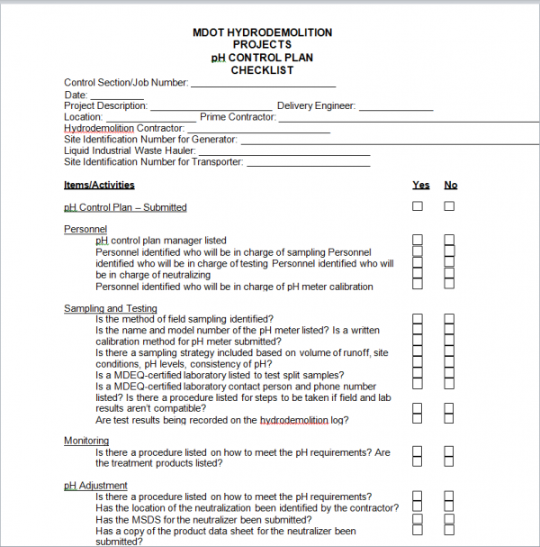
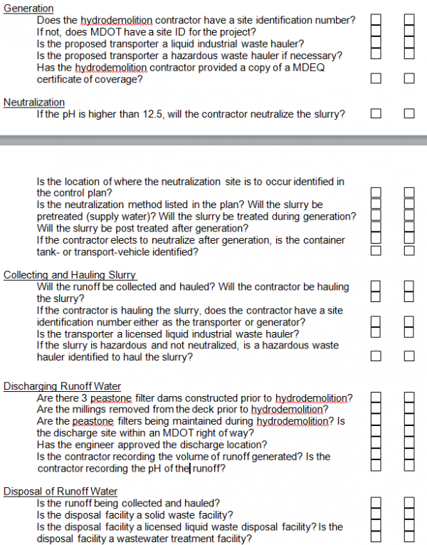
Hydrodemolition Project Checklist – see below for a sample. hydrodemolition project pH Control Plan checklist.
The contractor shall submit a hydrodemolition pH control plan for review and acceptance prior to beginning any hydrodemolition work. The following is a sample hydrodemolition pH control plan:
Equipment Description - see Section 712 of the Standard Specifications for Construction.
- SSPC-SP3 Power Tool Cleaning
Removes all loose mill scale, loose rust, loose paint, and other loose detrimental foreign matter by power wire brushing, power sanding, power grinding, power tool chipping, and power tool descaling. Coat the exposed structural steel after the SSPC-SP3 cleaning with 5 to 10 mils of aluminum-filled epoxy mastic before placing concrete. For deck replacement projects, the top flanges and beam ends should be cleaned and coated in accordance with section 715 of the Standard Specifications for Construction. Exposed reinforcing steel must be blast cleaned with an abrasive blast to remove loose scale and all rust. Ensure broken, missing or reinforcement bars that have lost ¼ of their original bar diameter is supplemented with additional reinforcement. Supplemental steel reinforcement should be lapped with the existing deck steel for a distance 35 times the bar diameter, per the Section 7 of the MDOT Bridge Design Guides, or as approved by the Engineer. After the loose material and debris has been removed and the steel reinforcement has been blast cleaned, flush the patch with clean pressurized water and remove any excess or ponding water with air blasting immediately prior to placing concrete. The existing concrete surface must be surface saturated to prevent it from robbing moisture from the green patch concrete.
Placing,Finishing, Curing Concrete
Mix and place patching material with equipment specified in subsection 703.03.B of the Standard Specifications for Construction. The surface of the patch must be moistened with no free standing water prior to placing patching material. For LMC patches, use a stiff bristle brush to apply an initial layer of the LMC mixture onto the wetted surface. The initial layer must be applied to both the horizontal and vertical surfaces of the patch. Limit the rate of progress so the brushed material does not dry before covering with overlay material. Place the concrete, vibrate and finish with a wood float. Texture the patch to a uniformly roughened surface. Ensure immediately after final finishing of each patch, the contractor applies a layer of wet burlap, which has been soaked for at least 12 hours, to exposed concrete surfaces. Place a 4 mil thick layer of polyethylene over the burlap to preserve the moisture in the burlap. Maintain the wet cure on non-LMC patches for 5 days or until a flexural strength of 550 psi is achieved. Maintain the wet cure on LMC patches for 48 hours, followed by 48 hours of air cure. Maintain the wet cure on high early mixes (QPL mixes or Bridge Deck Surface Repair (7 Sack) for at least 24 hours. The special provision for Bridge Deck Surface Repair (7 sack) mix special provision states that a 7 day wet cure is required for this type of patch. However, if a compressive strength of 2000 psi is achieved, the patch may be opened to traffic. Typically the 2000 psi compressive strength will be gained within 24 hours allowing the wet cure to be pulled and the patch opened to traffic. For this reason, the Bridge Deck Surface Repair is often substituted for LMC or Grade D patches.
Latex Modified Concrete
Latex Modified Concrete (LMC) is typically used for shallow overlays, deck patching or substructure patching of bridge rehabilitation projects. LMC may be hand mixed using the mixture proportions provided in table 703-1 in the Standard Specifications for Construction; however LMC is typically produced in mobile latex trucks which are calibrated by MDOT Bridge Field Services (BFS) prior to commencing work. Trucks must be calibrated at the beginning of each year (typically early spring) and every 6 months during the project if necessary. It is important to note that trucks are calibrated for multiple types of LMC mixture proportions. Substructure LMC, overlay and deck patching LMC and high early (HE) LMC have different mixture proportions and require adjustment of the mobile mixing equipment prior to placement. It is the contractor’s responsibility to contact BFS and schedule a field calibration of their truck(s). BFS will provide the necessary documentation to the engineer and provide the dial information to the field staff. Subsection 703.02 Table 703-1 Structures Patching Mixtures of the Standard Specifications for Construction lists the approved mixtures for structures patching. Included in the table are Latex Modified Concrete (LMC) mixtures and non-Latex Modified mixtures, all of which only require testing of air content and slump. Table 703-1 details the required air content in the far right column and Notes (a. and b.) of Table 703-1 detail the slump requirements as follows:
- Control water to provide a stiff, workable mixture with 1 in to 2 in slump. During hot and windy weather, the Contractor may increase slump to 3 in to 4 in, as determined by the Engineer.
- Add water, in addition to water in latex admixture, to control slump to within 3 in to 5 in. Measure slump from 4 min to 5 min after discharge from the mixer…
Due to the high compressive strength of the mixtures listed in Table 703-1 and the limitations associated with standard compressive strength testing equipment, cylinder testing for compressive strength is not required for these mixtures. However, the following cold weather limitations for LMC do exist as described in subsection 712.03.O of the Standard Specifications for Construction: If the air temperature falls below 50 ⁰F, the Engineer may require additional curing time to ensure concrete attains a flexural strength of 550 psi. Other mixtures approved for use in bridge deck patching such as the mixture detailed in the special provision for Bridge Deck Surface Repair (7 sack) require additional testing. Strength requirements will be as specified in Table 701-1A Concrete Structure Mixtures by Slump and 701-1B Concrete Structures Mixtures by Strength of Concrete of the Standard Specifications for Construction for Grade D concrete, and includes the following:
- The Contractor may use flexural strength to determine form removal. Use compressive strength for acceptance in other situations.
Quality control cylinders are not required for LMC and Silica Fume Modified Concrete (SFMC) used for bridge deck overlays. The contractor may be required to make beams depending on cold weather limitations, as listed in the subsection 712.03 R of the Standard Specifications for Construction. The contractor is still required to perform quality control testing for slump, air content and concrete temperature for these mixtures, however, quality control cylinders are not required from the contractor for these mixtures.
Mixing, Placing, Finishing, and Curing SFMC Concrete Overlays
See Section 712 of the Standard Specifications for Construction for trial batches.
Proportioning and mixing the SFMC overlay shall be by either a ready mixed or central mixed batch plant meeting the requirements of subsection 701.03. Trucks delivering SFMC to the project site must be fully discharged within one hour of charging at the plant.
One hour prior to placing the SFMC overlay, the prepared deck will be wetted with a uniform spray application of water. Water collecting in depressions will be blown out with clean, oil-free compressed air.
SFMC mixture placed in localized areas deeper than 3 inches (75 mm) is to be hand vibrated in front of the finishing machine by drawing a probe vibrator horizontally through the concrete parallel to the transverse reinforcing bars at intervals not greater than 18 inches (450 mm) on center. Should the operator have trouble locating the deep removal areas, the Contractor will devise a system for use such as a deck diagram or markings on the barriers. The Contractor will coordinate this system with the Engineer.
A continuous fog spray of water will be applied to the screeded and finished concrete to prevent net evaporation from the surface of the unhardened concrete. Fogging equipment will be capable of placing a fine mist over the concrete surface without ponding water. Fogging will continue behind the final floating operation until the wet cure system is in place and activated. Fogging shall not be used to apply water to the surface of the concrete to facilitate finishing.
The silica fume concrete overlay will be wet cured for 7 days according to Section 712 of the Standard Specifications for Construction.
Mixing, Placing, Finishing, and Curing Concrete Patches
See Section 712 of the Standard Specifications for Construction.
Substructure Repair
Areas to be patched or filled will be saw cut to a minimum edge depth of 1/2 inch (15 mm), and the concrete unsound or sound, will be removed to a minimum depth of 3 inches (75 mm). If resteel is exposed, chip 3/4 inch (20 mm) beneath the bar. Make sure the area is outlined with a saw cut to insure neat lines and no spall areas. After the concrete removal, blast clean the area to be patched. Forms must be cleaned, have a bond breaker applied, be tight and form neat lines. Place and cure patching material according to specifications.
MEASUREMENT AND PAYMENT
Measuring and Calibration
Prior to casting any overlay mixture, the finishing machine will be passed over the deck to check for plan thickness and the depths recorded on Form 1131 - Bridge Decks - Concrete Depth Measurements (see Figure 706-1).
Concrete Bridge Deck Overlay can be either a Silica Fume Modified Concrete or a Latex Modified Concrete.
Silica Fume Modified Concrete is required for Deep Bridge Deck Overlay Concrete.
|
|
|
|---|---|
|
|
Find an area of good concrete approximately 30 square feet (3 m2). |
|
|
Hydrodemolish approximately 10 square feet (1 m2). |
|
|
Using a straightedge, set it across the area, measure to the mortar line, and adjust depth as necessary. |
|
|
After the proper depth is obtained, the hydrodemolisher is ready for production cutting. |
|
|
After the machine has moved approximately 20 linear feet (6 m), recheck the cut depth and make any necessary adjustments. |
|
|
Now production can continue with spot checking the depth. |
|
|
Record the settings (water pressure, cutting head speed, forward advancement) on the IDR for future reference. |
|
|
During the first pass, the material will be cleaned up. |
|
|
No runoff water will leave the deck until it has been filtered clean. |
|
|
Allow the deck to air dry for one day before sounding the concrete for a second pass. |
|
|
Areas of exposed resteel and deep removal should be sounded for good concrete. Where resteel is debonded, the concrete will be chipped 3/4 inch (20mm) below the steel. |
|
|
Runoff water, filtered or unfiltered, shall not be allowed to enter storm sewers, bridge drainage downspouts or bridge approach downspouts, nor be discharged into surface water floodplains or wetlands. |
Testing of Latex Modified Concrete (LMC)
Slump, air and yield tests will be run on all trucks the first time around. Random testing will be allowed after this. The air test will be run immediately; the slump test after four to five minutes has elapsed. Yield tests will be adjusted by opening or closing the aggregate bins accordingly. New settings will be recorded for further use. No additives can be added for high or low air. If either of these conditions exists, a reblending of the latex is necessary. Out of specification material will be rejected.
Silca Fume Modified Concrete (SFMC)
Silica fume modified concrete (SFMC) is a concrete mixture used in rigid overlays to decrease the permeability of the concrete and thus increase the durability of the bridge deck. Silica fume is defined by the American Concrete Institute as “very fine non-crystalline silica produced in electric arc furnaces as a by-product of the production of elemental silicon or alloys containing silicon.” Particles of silica fume are considerably smaller than particles of cement. Therefore, the surface area of silica fume is greater and the water demands are higher. When used in conjunction with a water reducing admixture the SFMC has a low water to cement ratio and gains strength quickly. Due to the high water demands of the silica fume the mixture does not have excess bleed water to “give” and a timely and sufficient wet cure is crucial to the integrity of the overlay and to prevent shrinkage cracking of the rigid overlay.
One hour prior to placement of the SFMC the prepared deck should be wetted with a spray application of water. Excess water ponded in depressions should be removed with clean, oil free, compressed air. Proportion and mix SFMC using a ready mix or central mixed batch plant in accordance with subsection 701.03 of the Standard Specifications for Construction. During the placement, full depth patches and areas around joints may be filled full depth with SFMC. Areas that are deeper than 3 inches, should be hand vibrated to ensure consolidation of the SFMC.
Ensure the contractor applies a continuous fog spray of water to the screeded and finished concrete. Fogging should continue to be applied behind the final floating opeations until placement of the wet cure system (soaker hoses, wet burlap, etc). After placement, finishing and tining of the SFMC overlay the wet cure should be applied as soon as possible in accordance with subsection 712.03.Q of the Standard Specifications for Construction. It is not uncommon for wet burlap to be placed via the work platform within 10-15 minutes after placement.
SFMC overlays are typically used in overlays with an anticipated depth of 3-6”. Historically, a shallow overlay 1.5-3” consisted of LMC and a deep overlay 3-6” consisted of SFMC. With many rigid ove0rlays now incorporating crown and grade corrections, programmed shallow overlays quickly become deeper than 3” and thus SFMC is used. In the event that an SFMC overlay becomes deeper than 6” in more than a few isolated areas it may be advisable to investigate alternatives to SFMC. Alternatives such as slag cement overlays or high performance Grade D concretes may be used in lieu of SFMC with approval from the Engineer.
Epoxy Overlays
Epoxy overlays, or floodcoats have been used as a preventive maintenance treatment on bridge decks in Michigan since the mid 1990’s. The early floodcoats were a mix of thin epoxy overlays and penetrating sealers, much like today, however, they were expensive, time consuming and were of questionable effectiveness in terms of longevity. Since then, many improvements in material and application have been made through employee ingenuity and industrial innovations. By educating employees on the proper use and how to identify candidates for preventive treatments, fast, effective and long lasting floodcoats may be ensured to extend the life of Michigan’s structures.
- Floodcoats
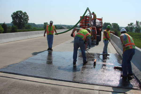
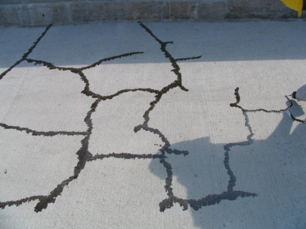
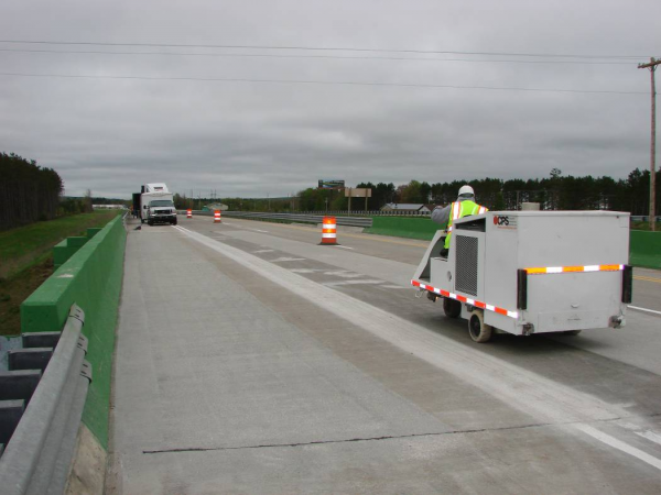
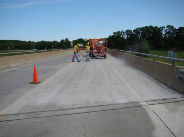
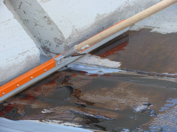
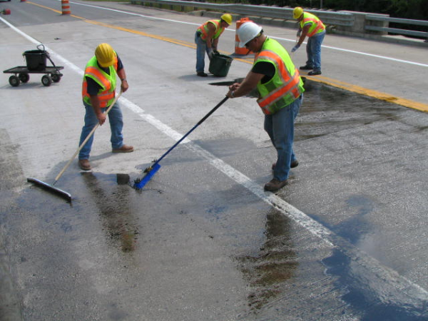
Floodcoat is a term used to describe the flooding of an entire bridge deck with a material to seal or bridge cracks to prevent moisture intrusion. While this term used to reference a thin epoxy overlay, it is in fact an application method and not an actual preventive treatment. Other methods of sealing cracks may be used, such as; crack chasing, spraying and rolling. The floodcoat method pours material on the deck and then squeegees or brooms the material over the entire surface, essentially flooding the deck. Floodcoating is typically used with thin epoxy overlays and penetrating sealers such as healer sealers, however, the term may be applied to other materials similar in nature.
- Choosing Method of Application
There are many factors to consider when choosing an application method for epoxy sealers. The primary factor is deck cracking. A simple rule to follow is the 2 foot rule. If the cracks are more than 2 feet apart, then crack chase each individual crack, if the cracks are less than 2 feet apart, then floodcoat the entire deck.
Other factors to include are size of the deck, causes of cracking, profile of the deck, need for skid resistance, traffic control and cost. If the deck is fairly large with cracks just under 2 feet apart, it may be more economical to chase these cracks versus flooding the entire deck. Whereas, a small bridge with cracks every 3 feet apart may benefit further from a floodcoat.
When investigating the causes of cracking one must interpret whether the cracks are caused by seasonal weather changes, concrete shrinkage or stresses in the deck. If the cracks are due to shrinkage or weather fluctuations, there may be many micro cracks that are not visible to the naked eye and thus require a floodcoat. If the cracks are due to local stresses in the deck, they may be better suited to a crack chasing operation to ensure significant penetration of the material.
The profile of the deck may also determine the method of application. A deck with heavy tining will require significant preparation work and material to floodcoat, especially a thin epoxy overlay. A smooth deck is easy to floodcoat, requires minimal preparation and will see a benefit in skid resistance from a floodcoat.
Often a bridge deck requires a high friction surface as well as sealant to increase skid resistance and prevent icing of the structure. In these cases a thin epoxy overlay floodcoat will seal the cracks and provide a high friction wearing surface.
- Thin Epoxy Overlay vs. Healer Sealer
Thin epoxy overlays and healer sealers, though both epoxy systems, are uniquely different. They both seal the cracks in bridge decks but do so in different methods. A thin epoxy overlay “bridges” the cracks in a deck. The thin epoxy overlay acts as a sacrificial layer on the bridge that prevents moisture from entering the cracks. It is a two coat system, each coat consisting of a layer of epoxy and aggregate. The epoxy is applied approximately 1/8 inch thick and followed by a layer of small aggregate, typically chipped flint, quartz or bauxite. Because this type of system does not penetrate and only bridges the cracks, it is imperative that the preparation to the deck prior to application be done properly. The preparation involves a heavy shotblast to remove any contamination and properly profile the deck surface. The overlay must bond to the aggregate in the concrete deck. The cement mortar is not strong enough to provide a proper bond and will result in a failure of the thin epoxy overlay. By shotblasting the deck heavily the top layer of mortar is removed and the aggregate in the deck is exposed. This ensures all contamination has been removed and allows the epoxy to bind to the large aggregate, creating a strong bond and preventing delamination of the overlay.
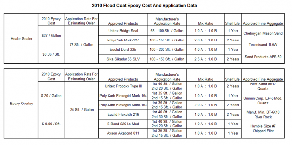
A healer sealer is a penetrating epoxy sealer. The viscosity of a healer sealer is approximately 50-80 centipoises (cps), whereas a thin overlay epoxy has a viscosity of approximately 2000 cps. To further understand, water has a viscosity of approximately 1 cps and honey 2000-3000 cps. A healer sealer is a one coat system that involves flooding the deck with the epoxy penetrating sealer and broadcasting a dry mason’s type sand over the epoxy to maintain skid resistance. Unlike the thin epoxy overlay, the healer sealer penetrates the cracks to seal them and therefore, is not as dependant on deck preparation. A quick shotblast is still necessary to remove contaminates and “open up” the cracks in the deck. Through shotblasting, the cracks’ edges are rounded off and any debris in the crack is removed, allowing the healer sealer to further penetrate the crack. Any epoxy on the deck surface that doesn’t penetrate is meant to wear off in time. The epoxy that penetrated the cracks remains and continues to prevent moisture intrusion.
As a result of less preparation and only requiring one coat, a healer sealer is more economical than a thin epoxy overlay. A healer sealer requires half the material, a much less expensive aggregate and a third of the time to complete. However, they both have their advantages and disadvantages.
Technical Data
Skid Resistance
Skid resistance is measured by determining the Skid Number (SN). The SN is a measure of the frictional resistance to motion (F) divided by the load perpendicular to the interface (L) multiplied by 100.
SN = F/L(100)
A SN greater than 35 is acceptable for heavily traveled roads. Typical bridge decks throughout the state have a SN between 35 and 45.
A thin epoxy overlay will increase the SN of a bridge deck to approximately 65. This is a significant increase in skid resistance. A healer sealer will increase or maintain a SN of 45. It will temporarily increase the SN of a smooth deck and maintain the SN of other decks. After the healer sealer has worn off, the deck will return to the original SN.
Viscosity
Viscosity is a measure of a fluid’s resistance to flow. Unlike density or specific weights, which are defined as a fluids mass or weight per unit volume, viscosity is an additional characteristic that is helpful to determine how a fluid will act under a shearing stress such as a squeegee.
Knowing the viscosity of a material is helpful in understanding its characteristics during epoxy application. A higher value will require more effort to spread across the concrete surface and dictate whether or not it penetrates cracks. For example, if a similar amount of pressure is exerted on two separate squeegees spreading Unitex Bridge Seal (40 cps) and Euclid Dural 335 (80-100 cps), the Bridge Seal epoxy will spread further covering additional surface area. The variation of viscosity values emphasize the importance of documenting square feet coated and volume of epoxy for each application.
Comparing the viscosity values in Table 712.04.02 and Table 712.04.03 help display how one method “bridges” cracks and the other penetrates them. The smaller values for healer sealer indicate the mixed material can flow easily into tight cracks. The larger numbers for thin epoxy overlay indicate the material remains on the deck surface. Typical application rates for healer sealer are 100 square feet per gallon. However, variations in viscosity may increase/decrease rates by as much as 50 square feet per gallon.
Thin Overlay Surface Preperation
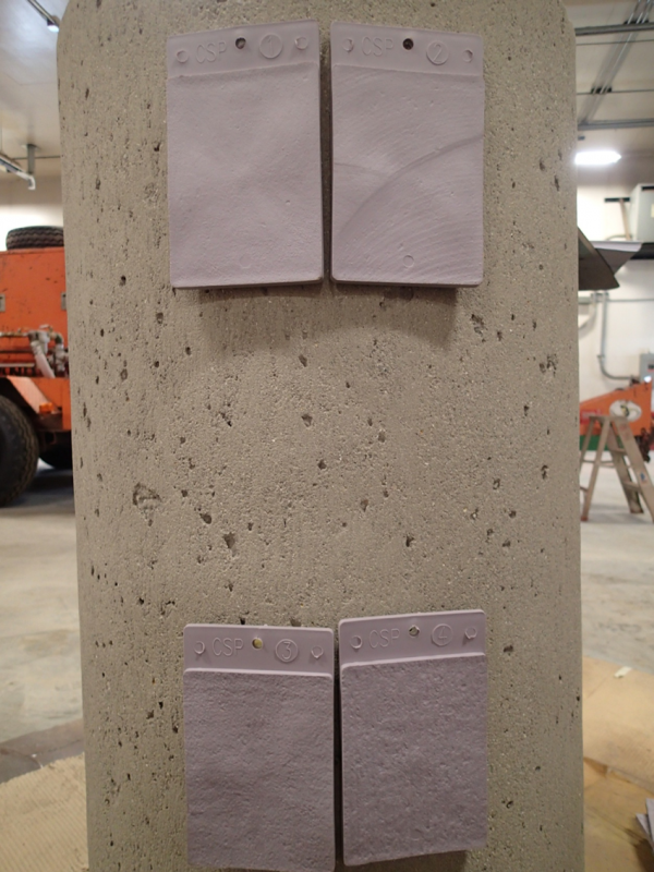
Ensure the contractor adequately shotblasts the deck surface to remove oils, dirt, curing compounds, weak surface mortar and other contaminants. The velocity of the shotblaster and number of passes across a surface determine the Concrete Surface Profile (CSP). Usually three or more slow passes are required to achieve a concrete surface profile of seven. Because steel shotblasting may create surface profiles ranging from three to eight it is important to understand the surface roughness required for proper bonding of the epoxy. The International Concrete Repair Institute Guidline (ICRI) No. 03732 defines the surface profiles and classifies them on a scale of 1 to 9.
Description of surface profiles:
- CSP 1 – Acid Etched
- CSP 2 – Grinding
- CSP 3 – Light Shotblast (Healer Sealer)
- CSP 4 – Light Scarification
- CSP 5 – Medium Shotblast
- CSP 6 – Medium Scarification
- CSP 7 – Heavy Abrasive Blast (Thin Epoxy Overlay)
- CSP 8 – Scabbed
- CSP 9 – Heavy Scarification
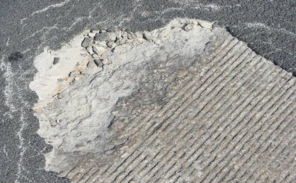
Ensure that when placing a thin epoxy overlay, the deck tining is removed to achieve a profile of CSP 7. However, if hard natural aggregate is present there may still be portions of the tining visible. In either case, a layer of aggregate in the deck should be exposed without mortar covering it. See Figure 712.9 for an example of improper surface preparation; the deck tining of the concrete has not been removed resulting in a CSP 3 and there is an area of unsound concrete.
Paint striping acts as a bond breaker and must be removed. A shotblaster may achieve the proper profile where striping is not present, but extra attention with the shotblaster or a line grinder is often needed to remove paint. If any unsound areas are discovered during shotblasting they should be repaired and the overlay application delayed. All patches, regardless if fast setting, have to cure for a minimum of 28 days.
After shotblasting is complete vehicles are not allowed on the prepared surface prior to completing both courses of the overlay. In the event the lane has to be opened, the surface must again be prepared with a light shotblast. Proper planning will reduce the amount of repetitive shotblasting occurrences.
Healer Sealer Surface Preperation
Shotblasting must also be performed prior to applying healer sealer; however, the level of preparation is far less than that of a thin epoxy overlay application. The purpose of shotblasting for a healer sealer has less to do with preparing a bonding surface and more to do with rounding crack edges and facilitating penetration of the epoxy. A concrete surface profile of CSP 3 from ICRI Guideline No. 03732 is easily achieved by a light shotblast. Usually tining is not removed nor is aggregate exposed, but the surface should be visibly lighter in color.
Traffic may be placed on the prepared surface of a healer sealer for approximately one week after achieving the required surface profile. The ability to reopen lanes is helpful when contracting shotblasting because the same traffic control devices may be used at multiple structures. With proper planning, multiple structures in the same corridor may be shotblast in a single day and later treated, decreasing affects to mobility.
Final Cleaning
Expansion joints should be taped off prior to spreading epoxy. Removing cured epoxy from strip seal joints often damages the gland and may lead to deterioration of the beams, bearings, and substructure as a result. If deck drains are present they should be taped well to prevent the release of epoxy to a roadway or surface water below.
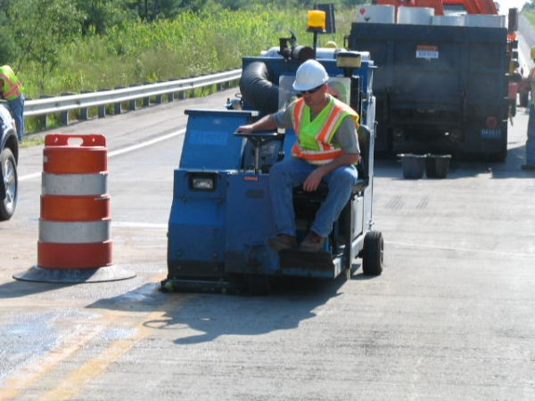
A rolling magnetic sweeper is helpful to retrieve steel shot for reuse and reduce the amount of particles on the deck. Clean the deck with dry compressed air after shotblasting to remove any dust or loose particles from the cleaning operation. A vacuum truck may not be used in lieu of compressed air.
Moisture Testing
Moisture testing must be completed on all contracted projects, and also when the presence of moisture is suspected during an application by direct forces. An 18 inch x 18 inch 4 mil polyethylene sheet must be taped to the deck for at least two hours to determine if moisture is present. Moisture will be identified by condensation on the sheet. The procedures of the test method are specified in ASTM D 4236. It is important to ensure the bridge deck is dry prior to placing a floodcoat. Special attention regarding moisture should be given to those bridges with side by side box beams and stay-in-place forms.
Application Temperature and Weather
The minimum recommended air and surface temperature for proper curing of epoxy is 50°F and rising. If moisture is present or precipitation expected within eight hours do not place epoxy. Removing a floodcoat is an expensive endeavor using specialized equipment that is not readily available.
Mixing
When daytime high temperatures will not reach 70°F epoxy and aggregate should be stored in a warm location for several hours prior to placing at the site. If it is either impractical or impossible to keep both materials warm, drum heaters set at 100°F should be used to ensure the epoxy is not too viscous for proper mixing.
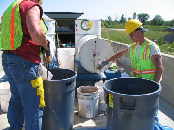
Mixing the epoxy must be done in a controlled fashion to eliminate any variances during the process. Ratios range from 1:1 to 4:1 depending on the brand. The epoxy should be measured in containers that are clearly labeled “A” and “B”. After measuring the correct portions, place them in an oversized mixing container of 150 percent larger volume to prevent spills. Placing a tarp underneath the mixing containers and having an absorption kit nearby is helpful to capture any spilled material.
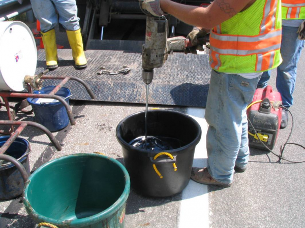
Use a half inch electric or gas powered drill with a jiffy mixing paddle. Keep the entire paddle beneath the surface of the epoxy to prevent entraining air. All brands need to be mixed for exactly three minutes. A watch or other timing device must be used for accuracy. Less mixing will lead to improper curing and jeopardize adhesion of the product. Over mixing may result in premature setting of epoxy in the mixing containers.
Pumps are available that mix the epoxy at the nozzle. These pumps are calibrated based on the epoxy being used and the required mixing ratio established by the manufacturer. It is the contractor’s responsibility to ensure proper calibration of pumping equipment, however, it is wise to verify calibration is correct prior to beginning application.
Applying Epoxy
After mixing is complete, it is important to spread epoxy in a timely manner. Epoxy should be spread within five to ten minutes at surface, air, and material temperatures above 70°F. During cooler temperatures the product may be purposely held in the container for no longer than ten minutes to speed cure time. The container should be emptied completely after each batch to prevent cured material from being placed that will eventually scale from the deck.
Thin epoxy overlays are two course systems. The application rate for the first course must be a minimum of 40 square feet per gallon. After pouring the mixed material onto the deck, notched squeegees shall be used to distribute the epoxy evenly. Traffic is not permitted to be placed on the first course at any time. After the first course has cured, broom or blow all excess aggregate from the deck prior to placing the second course. The same process is used for the second course; however, the application rate shall be a minimum of 20 square feet per gallon.
A healer sealer is a one coat system that is applied at approximately 100 square feet per gallon. Once the material is mixed it is spread using squeegees or brooms. Brooms are especially helpful to spread epoxy on tined surfaces. Excess epoxy must be removed from tined surfaces of the deck to maintain the existing profile and SN.
Aggregate Placement
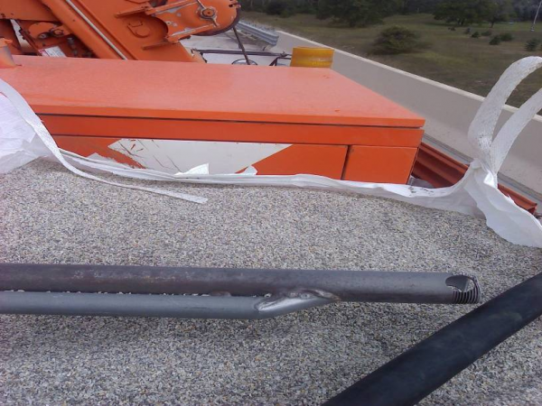
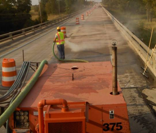
There are multiple techniques to spread aggregate. Broadcasting by hand (“chicken feeding”) or using a gravity fed spinning distributor such as a fertilizer spreader is effective, but may be labor intensive and result in excessive waste. The most popular method utilizes a 375 cfm or 750 cfm air compressor connected to a venturi system. A vacuum is created by the venturi that draws aggregate from a 3,000 pound jumbo sack and distributes it onto the freshly placed epoxy through a 4 inch hose. An applicator directs it so no wet spots are visible. If epoxy bleeds through it the area should be covered with additional aggregate. One hose can be used to spread aggregate, but for large structures or experienced crews, two hoses will expedite the process. For two operations, a 750 cfm air compressor shall be used.
Multiple suppliers of aggregate are approved for thin epoxy overlays that exhibit the required Moh’s hardness of seven or greater. The high degree of hardness allows the approved materials such as quartz, river rock, and chipped flint to provide exceptional skid resistance for multiple seasons. The aggregate must remain dry prior to and during placement. Aggregate is spread at approximately 3.33 pounds per square foot and the material is often packaged in 3,000 pound waterproof sacks.
Fine aggregate (sand) is used for a healer sealer application. The sand must be applied to excess and provide a dry appearance to the deck after placement. If the surface appears wet additional sand will need to be placed immediately. The sand should be spread at a rate of at least 1.5 pounds per square foot. Sand is often shipped in 2,300 pound waterproof sacks. Traffic may be reestablished after the epoxy has cured and excess sand has been removed.
=== Substructure Patching===
Substructure patching includes patching those areas of the bridge not considered the bridge deck, such as abutments, pier columns, pier caps, barrier wall, wing walls, etc. This work will consist of saw cutting the boundaries of the area to be patched, hand chipping the deteriorated concrete, preparing the patch and forming, finishing and curing the new concrete patch.
Saw Patching
Areas to be patched should be saw cut to a depth of ½ inch and squared off the best they can to facilitate removal of the deteriorated concrete and provide a clean edge for the new concrete to bond to. Take care to not set the saw depth so deep as to cut the reinforcing steel. Any reinforcing that is cut will have to be supplemented with additional steel, by lapping the existing or epoxy anchoring into the adjacent concrete to achieve the desired develop length.
Hand Chipping
Hand chip the deteriorated concrete with pneumatic chipping hammers or other methods approved by the Engineer. The concrete must be removed to a minimum depth of 3 inch or until reinforcing steel is encountered. When reinforcing steel is encountered concrete must be removed at least ¾ inch behind the bars to allow for the new patch to bond with the existing materials. The 26A aggregate in the patching material has a maximum diameter of ½ inch. The ¾” inch clearance around the reinforcing steel, allows the ½ inch aggregate to engage the steel and provides good concrete consolidation in the patch.
Patch Preparation
After the patch has been squared up, saw cut and hand chipped, the patch must be prepared via abrasive sand blasting. The abrasive sand blasting cleans loose material and contaminates from the patch. The abrasive sand blasting must also remove loose rust and scale from the exposed reinforcing steel. If after blast cleaning the exposed steel is found to have lost more than 1/4 of the existing bar diameter due to corrosion, the bar must be supplemented with additional reinforcement. Install forms for vertical patches no greater than 4 foot high sections, with the form tops no more than 4 feet above the concrete level as the pour progresses. After the patch has been abrasive blast cleaned, all necessary reinforcing steel supplemented and forming completed the patch must be wetted immediately prior to pouring the Latex Modified Concrete (LMC) or other approved patching mixture.
Substructure Patch Concrete
See 712.02.E of this manual for the information regarding the LMC concrete mixture for substructure patching. Immediately after placing the concrete apply a layer of wet burlap, which has been soaked in water for at least 12 hours, over the patch. Curing compound may be used in lieu of wet burlap on non-LMC patches. The contractor may also leave forms in place and only cover exposed surfaces accordingly. Any mix with latex must get the wet cure or leave forms in place during cure. Ensure the contractor keeps LMC patches wet during curing for the first 48 hours and allow to air cure for an additional 48 hours. Patches that are neither LMC nor High Early must remained covered for at least 5 days AND until a flexural strength of 550 psi is attained. High Early patches must remain covered for at least 24 hours. High Early LMC patches must remain continuously damp for 24 hours.
Expansion Joints
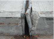
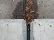
Expansion joint performance is important to the long term durability of a bridge. They protect the structural elements below them from moisture and debris that may result in deterioration of concrete or corrosion of structural steel, while allowing the bridge to expand and contract as designed. It is important that expansion joints are installed properly during new construction and reinstalled correctly during rehabilitation projects.
New Construction
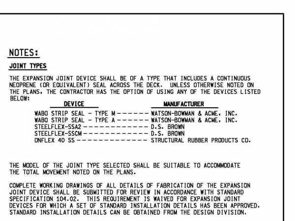
New designs may incorporate sleeper slabs and structural approaches to keep expansion off of the bridge. This method of allowing the bridge to expand and contract outside of the limits of the bridge, prevents damage to the structure in the event that an expansion joint fails or leaks. The sleeper slab design uses a large T shaped concrete foundations (sleeper) to carry both the road approach and the structural approach to the bridge. The large T shaped sleeper prevents settlement of the approach at this location. The structural approach is reinforced similarly to a bridge deck and is designed to carry the design load in the event the structural back fill below is washed out. Below the structural approach and sleeper slab, open-graded drainage course (OGDC), or aggregate base compacted at 98% should be used to facilitate drainage and prevent loss of material. This type of sub grade in conjunction with the concrete sleeper will prevent settlement and provide a smooth transition from the road to the bridge. The expansion joint rail is installed at the joint between the sleeper slab and the structural approach. The following detail provides the information regarding proper installation and the approved types of joints that may be used on MDOT projects.
Expansion joints (EJ3's) consist of two galvanized steel rails, approximately 1.5" wide by 2.5" deep. The joint is comprised of a system of galvanized steel anchors that are cast into the adjacent concrete. The front side of the rail contains a recess that receives the neoprene gland. The rails are typically supplied in 22' sections bolted together with a 2" opening. The rails may be cut and field welded to match the contour of the bridge or roadway. All welding must be done by a certified welder and welding procedure specifications must be submitted by the contractor to the Engineer for approval. It is a best practice to weld joint rails together near centerline, or lane lines. Welded joints near wheel paths should be avoided is possible. Though the anchors are cast into the concrete to keep them in place, it is also a best practice to wire tie the steel anchorage into any intersecting deck steel, sleeper slab steel, or approach reinforcement. This extra measure will further secure the rail and increase the durability of the joint in the event the adjacent concrete deteriorates. Prior to casting the concrete adjacent to the joint rail, the rail should be set to the proper elevation matching the existing profile of the roadway and/or structure. The rail should be recessed approximately ¼ inch below the surface of the roadway or deck to prevent snow plow damage. The joint must have upturns that match the existing brush block, parapet or barrier. The upturn will capture moisture and debris and prevent this from leaching down the fascia, or eroding the approaches. Upturn should also be recessed into the brush block, parapet or barrier wall to prevent snow plow damage. Any portion of the steel rail protruding from the concrete is susceptible to snow plow damage and may result in a joint failure.
After the joint is set properly and tied into the adjacent reinforcing steel and all form work is complete, the concrete may be poured. It is a best practice to tape over the recess in the joint rail to prevent slurry from entering the recess. Any hardened concrete slurry in the recess will make it difficult to get the neoprene gland installed. Good vibration practices are crucial to achieve proper consolidation around the congested steel and anchorage at the joint locations. Improper consolidation will result in voids, premature joint failure, concrete spalls and will result in need for a joint replacement. Immediately after the concrete pour, the bolts keeping the two sections of joints spaced at 2" should be cut. If the bolts are not removed prior to the concrete curing, the slightest thermal expansion or contraction will result in cracking of the adjacent concrete. After the concrete has been cured properly, the tape over the recess and any form work may be removed. The neoprene gland can be may be installed with a combination lubricant adhesive, approved by the joint manufacturer. The gland must be installed in one continuous piece, or spliced through cold vulcanization as approved by the manufacturer.
Expansion Joint Replacement
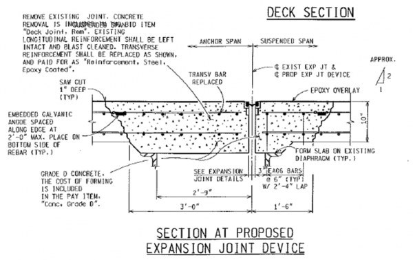
Expansion joint replacement is similar to a new installation, however; the old joint must first be removed. To remove the existing joint, a 1" saw cut should be made a minimum 1 foot 6 inches either side of the joint, or per plans. This dimension may vary depending on the amount of concrete deterioration adjacent to the joint, the skew of the structure, or the distance to the pier or end diaphragm. If the joint replacement is part of a larger rehabilitation project incorporating a rigid overlay, the saw cut is not required. However; if the deck is to remain intact, the saw cut is necessary to provide a clean edge for the new concrete. After saw cutting the entire width of the bridge deck the concrete may be removed via pneumatic hammers. The contractor may only use 60 pound pneumatic hammers or smaller within 6" of the transverse saw cut or within 12" of any beam line. On steel beam bridges, 300 pound equipment mounted hammers may be used outside of the beam lines and away from the transverse saw cut. Equipment mounted hammers are NOT allowed on concrete beam bridges, removal is limited to 60 pound hammers.
Concrete should be removed full depth across the entire joint and through the barrier wall, brush block and/or parapet. It is imperative that the joint is free to move across the entire cross section of the bridge deck. Any concrete in or adjacent to the joint left in contact (or less than 2 inches) including areas in the barrier and bridge fascia may prevent the bridge from expanding and damage other elements of the structure. Abrasive blast clean the prepared area to remove loose concrete and to remove scale or accumulated rust from the reinforcing steel. Replace exposed transverse bars and supplement any exposed bars that have lost a ¼ or more of their original bar diameter. Supplemental steel must be lapped or anchor appropriately to achieve development of the reinforcing steel. Lap bars at least a distance 35 times the bar diameter. Tie lapped bars in at least two locations and tie bar intersections at every third intersection. Install galvanic anodes to uncoated reinforcement along the perimeter of the joint repair. Space anodes as shown on the plans, but do not exceed 24 inches.
Form the slabs as shown on the plans. Forms on the underside must be flush with the bottom of the bridge deck. Squaring up of any rough edges on the underside of the bridge deck will facilitate good consolidation and prevent honeycombing of the concrete. Set rail according the new joint installation procedure above. Adjacent concrete must be cleaned with dry, oil free compressed air to remove any loose material and/or debris. The concrete must be moistened prior to placement of the new concrete. Any excess water should be removed with clean, dry, oil free compressed air. Place Grade D concrete or an approved substitute. Often, when dealing with SFMC rigid overlays, SFMC may be used in lieu of the Grade D. Also, if no other Grade D is set up on the project a Bridge Deck Joint Repair (BDJR) mix may be substituted for the Grade D. The BDJR is a 7-sack mix with a smaller 26A coarse aggregate to help achieve consolidation around the congested resteel near the joints. The BDJR typically achieves 2000 psi compressive strength within 24 hours and can be opened to traffic, making this suitable mix for projects that must be open to traffic quickly. After placement of concrete, apply a layer of wet burlap (which has soaked for at least 12 hours) over the fresh concrete. Cover with a 4-mil thick layer of polyethylene until the concrete has reached the desired strength.
Sidewalk Plates
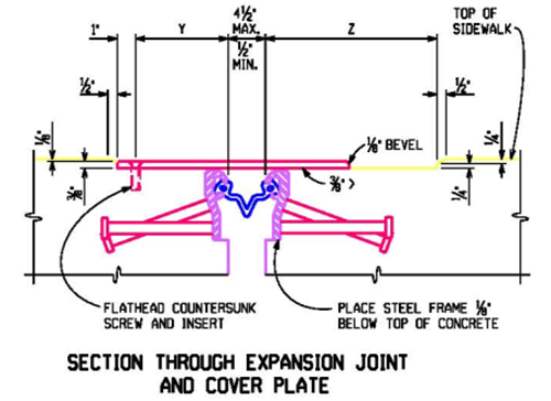
All steel for expansion joint cover plates at sidewalk locations shall be AASHTO M270, Grade 36 and galvanized with a static coefficient of friction of 0.6 or greater. Use ASTM F 593 (Type 304) stainless steel 3/4" diameter flathead countersunk screws with 3/4" diameter inserts. Prior to placement of the sidewalk plates, grind the concrete to be below the plates smooth and apply one coat of epoxy resin to facilitate sliding of the steel plates. The steel plates must be recessed to avoid a tripping hazard a minimum 1/4" inch. This recess may to provide through forming of grinding of the concrete. Install the plates so that the screws and inserts are on the high side of the joint to prevent moisture penetration on the low side.
Repairing Cracks By Sealing/Pressure Injection
Cracks in concretes may lead to moisture penetration which in turn may lead to freeze/thaw damage or corrosion of reinforcing steel. Crack sealing is a method of filling or sealing the cracks with a topical or gravity fed application of epoxy or other material which “bridges” smaller cracks or fills wider gravity fed cracks and prevents moisture penetration. Crack injection involves porting into the crack and forcibly injecting the crack with material under pressure, filling the crack and preventing moisture penetration. Crack sealing is typically conducted in bridge decks or other horizontal surfaces, where the cracks are gravity fed with a low viscosity sealant, or on smaller cracks in vertical surfaces that can be “bridged” with a higher viscosity material. Crack injection is necessary on wider cracks in vertical surfaces that cannot be “bridged” by topically applied products. When cracks in vertical or overhead surfaces are 0.002 inches in width or greater, crack injection is recommended. For cracks less than 0.002 inches in width, crack sealing is recommended.
Crack Sealing
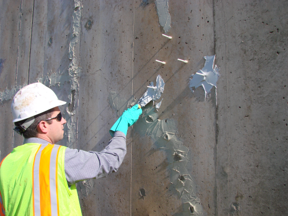
Crack sealing in bridge decks is effective for those bridge decks with few cracks not warranting a complete flood coating of the deck. The cracks are prepared for sealant by lightly abrasive blasting the crack and 1 inch to 2 inches either side of the crack to remove debris, clean the adjacent surface and open up the crack to facilitate penetration of the epoxy sealant. The approved sealant (typically a two part epoxy) is mixed per the manufacturer’s recommendation and applied to the crack until refusal providing a 1 inch overband the entire length of the crack. The approved crack sealing products can be found in the Qualified Products List (QPL) section of the Sealing Localized Cracks special provision. After application of the epoxy sealant, the uncured epoxy may be lightly coated with a dry mason sand to prevent tracking, and opened to traffic. Cure times of the epoxy vary from 1 hour to 12 hours depending on the temperature. Epoxy should only be applied when temperatures are 40 degrees Fahrenheit and rising. Sealing of thin cracks (less than 0.002 inches) in vertical surfaces consists of the same preparation as the sealing of cracks in bridge decks. However; the epoxy will not penetrate the crack. A more viscous material is used to bridge the crack with a minimum 1 inch overband. Vertical cracks can also be sealed with concrete surface coating. Elastomeric concrete surface coatings offer some flexibility and are able to move with expansion and contraction of the concrete, offering a long term seal for the cracks. Concrete surface coatings are applied to the entire given area of concrete per direction of the plans. The concrete surface is prepared through power washing or abrasive blasting and is applied per the manufacturer’s recommendations.
Crack Injection
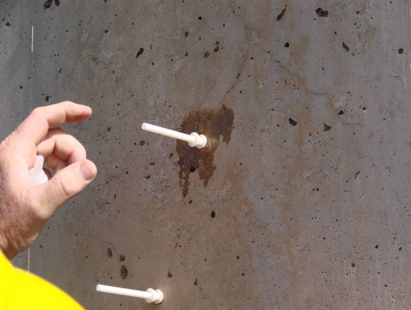
Crack injection involves pressure injecting of cracks to seal wide cracks (greater than 0.002 inches) in vertical surfaces. The cracks should be flushed out by means of power washing with water until clean. The cracks should be dry and free of contaminates prior to commencing the injection. Ports are glued to the crack with an epoxy adhesive and spaced based on the desired penetration of the injection material. For example, a 9 inch thick slab should have a 9 inch port spacing to penetrate the entire slab. After placement of the ports, the epoxy resin is applied to the top of the cracks and around the ports to seal the top of the crack and to prevent leakage of the material under pressure. The injected material will travel radially until the next closest port offers relief of pressure. After the epoxy resin has cured the ports may be injected.
Ensure the contractor begins injection at the lower entry port and continue pumping until the epoxy material is visible from the port directly above it. Stop injecting and cap the first port and transfer the injector to the next port. Continue this method for the length of the crack. For considerably deep members that have a full depth crack, injection may need to take place on both sides of the member if both sides are accessible.
Approved epoxy resins and sealants can be found in section 914.06 of the Qualified Products List located in the Materials Source Guide. Epoxy resins and sealants should be mixed and applied per the manufacturer’s recommendations. All epoxy should be applied when temperatures are in excess of 50 degrees Fahrenheit and allowed to cure per manufacturer’s recommendations prior to loading or as determined by the Engineer.
Carbon Fiber Repair
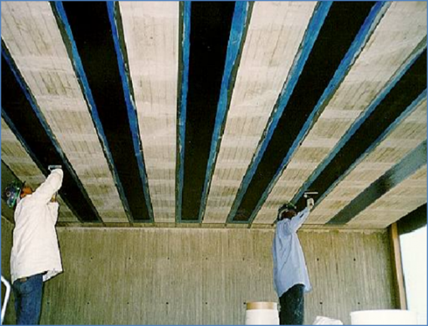
Carbon fiber repairs consist of wrapping vertical and horizontal concrete structural elements for concrete confinement of concrete columns, and increased shear and tensile capacity of concrete beams. Carbon fiber has high tensile strength, however; is weak in shear and susceptible to impact damage. When installing carbon fiber for a given repair it is important to be aware of the direction of the carbon fiber fabrics and ensure they are acting in the same direction as the intended forces. Carbon fiber sheets are typically produced in uni directional weaves 20” in width. However, multi-directional sheets can be ordered as well.
Carbon Fiber Application
Before the application of carbon fiber reinforcement for any type of repair, any delaminations in the concrete must be removed and patched, corroded steel must be repaired and free from rust and scale and any concrete cracks larger than 0.010 inches must be injected. Cracks, spalls and other deficiencies in the concrete will jeopardize the integrity of the carbon fiber wrap. Patched concrete must cure for 28 days minimum prior to application of the carbon fiber. Injected cracks must cure per the manufacturer’s recommendation prior to carbon fiber application. After all deficiencies in the concrete have been addressed the surface of the concrete must be prepared for the carbon fiber material. If the material will wrap around a beam or rectangular column, sharp corners must be ground down to provide a 1 inch radius. Sharp edges and corners will result in failure of the carbon fiber wrap at those locations. The concrete surface must then be prepared to a CSP 3 profile, but no greater than a CSP 4. All dust, laitance and other contaminants must be removed prior to application. Typical methods of achieving the proper profile are abrasive blast cleaning, water blasting and/or grinding.
The carbon fiber system utilizes three different epoxies during the application process. A primer, putty and a saturant are the types of epoxies used. It is important for the concrete to be clean and dry prior to beginning application. First the epoxy primer is applied with a nap roller or bristle brush. The primer is applied to all areas to receive the carbon fiber. The putty is then applied (preferable before the primer cures) to fill in all the voids and deficiencies in the concrete. A roughened concrete profile will use more putty than smooth concrete surface. The goal of the putty is to provide as smooth a profile as possible for the carbon fiber material. Next the saturant is applied and the carbon fiber material placed over the epoxies while the saturant is still wet. A rib roller will facilitate placement of the carbon fiber wrap and work out any air voids. The saturant should bleed through the carbon fiber fabric. After the carbon fiber has been placed, a second coat of saturant is applied over the surface of the newly installed carbon fiber wrap. To ensure complete fiber encapsulation by the saturant, an auto-impregnator should be used when possible. The wrap end and each subsequent layer of wrap must overlap at least 12 inches.
Carbon Fiber on Concrete Beams
Carbon fiber may be used on concrete beams to increase the shear capacity at the beam ends and also to increase the flexural strength of the beams in high moment regions. For shear strength applications the beams are wrapped vertically around the cross section of the beam near the bearing location. It is important that the beam end is square and not “I” shaped. Box beams are suitable for this type of application. Ensure corners are rounded to a 1 inch radius for application when wrapping around them. Properly applied, the CFRP wrap will add shear capacity of about 1 kip per inch. of beam depth for a U-wrap configuration. For prestressed concrete I (PCI) beams, the I-section to be wrapped should be built up to a square section prior to the shear strengthening. For flexural strength applications the carbon fiber sheets are applied along the bottom of the bottom flange in the longitudinal direction of the concrete beams. See Figure 712.29 for a typical application. This may be applied to both PCI beams and box beams with no additional modifications to the beams. If the repair does not extend the full length of the beam, it is important that the CFRP sheets extend sufficiently beyond the repair section to develop the full capacity of the epoxy bond. Using 1.3 x the development length is a good guide. For a single layer of 9-oz./syd CFRP fabric with an elastic modulus of 33,000 ksi, the minimum development length is 3 inches, and the wrap should extend 1.3 x 3 inches, or 4 inches. The plans will indicate the limits of CFRP fabric application (which will include the development length) for construction projects.
Carbon Fiber or Structure
Carbon fiber wrapping is typically conducted on substructure pier columns as a method of confinement. When a substructure unit has many concrete spalls or delaminations, the concrete may be repaired and a carbon fiber wrap applied to maintain the integrity of the existing concrete and prevent further spalls in the future. CFRP wraps are not recommended for square columns with side aspect ratios greater than 2.0, or face dimensions exceeding 36 inches. The wrapping of columns is completed by applying the carbon fiber sheets around the column or pier. The sheets are overlapped approximately 4 inches to provide 100% confinement of the concrete to the desired height needed along the column. Multiple layers of carbon fiber wrapping may be used to “stiffen” the column and increase the bearing capacity. The increase of bearing capacity technique is typically utilized in seismic regions, whereas most MDOT applications are focused on confinement and protection of the existing concrete and reinforcing steel. Carbon fiber wraps are susceptible to ultraviolet (UV) damage and therefore for applications such as column wrapping that may be exposed to sunlight, coat with a concrete surface coating to protect the carbon fiber from the UV rays.
Grouting Under Masonry Plates
Grouting is a technique used to restore bearing under bearing masonry plates when concrete below the bearing has deteriorated to the point capacity is affected, or during bearing replacements that may change the elevations from the existing bearings. The contractor must propose grouting procedures to the Engineer for approval. Typical procedures involve forming the sides with plywood or other materials and placing grout from the top, or forming all areas and pressure grouting with weep holes/tubes to remove entrapped air. The contractor must demonstrate through means of a mock-up that the grouting procedure can achieve at minimum 90% of surface area contact below the bearing. Any substructure concrete placed prior to grouting must reached the required compressive strength prior to grouting. The surface to receive the grout must be clean and free from debris prior to grouting. Form the space for grouting and mix, place and cure the grout according the manufacturer’s recommendations. Approved grouts for MDOT projects may be found the QPL. After curing the forms may be removed and the structure lowered after the required compressive strength of the grout has been gained. Grout cubes may be necessary to verify the compressive strength requirements. Typical grout pad thicknesses vary from a minimum of 1 inch to a maximum of 6 inches without the need for grout modifications. For thicknesses above 6 inches, multiple lifts, coarse aggregate or resteel may be required to prevent overheating and/or cracking of the grout.
