Difference between revisions of "714 - Temporary Structures and Approaches"
m (Removed 2012 Spec Book tagline link) |
|||
| (6 intermediate revisions by 2 users not shown) | |||
| Line 4: | Line 4: | ||
<center><span STYLE="font: 40pt arial;">'''Temporary Structures and Approaches'''</span></center> | <center><span STYLE="font: 40pt arial;">'''Temporary Structures and Approaches'''</span></center> | ||
| − | |||
| Line 186: | Line 185: | ||
* Bolted and welded joints are constructed per plan. | * Bolted and welded joints are constructed per plan. | ||
| − | Ensure removal of falsework supporting structural concrete elements is not done prior to the concrete attaining 70% of the specified 28-day flexural or compressive design strength, and for at least 5 days following concrete placement per [http://mdotcf.state.mi.us/public/specbook/files/2012/706 | + | Ensure removal of falsework supporting structural concrete elements is not done prior to the concrete attaining 70% of the specified 28-day flexural or compressive design strength, and for at least 5 days following concrete placement per subsection [http://mdotcf.state.mi.us/public/specbook/files/2012/706%20Str%20Conc%20Construction.pdf 706.03.O] of the Standard Specifications for Construction. |
{{top}} | {{top}} | ||
| Line 194: | Line 193: | ||
Prefabricated or Modular type formwork is typically reused on many different projects. Inspect the formwork when the components arrive on site, and ensure only components that are in good condition are used. | Prefabricated or Modular type formwork is typically reused on many different projects. Inspect the formwork when the components arrive on site, and ensure only components that are in good condition are used. | ||
| − | Measure the inside openings of the forms, and compared to plan dimensions for formed elements. Ensure tolerances [http://mdotcf.state.mi.us/public/specbook/files/2012/706 | + | Measure the inside openings of the forms, and compared to plan dimensions for formed elements. Ensure tolerances per subsection [http://mdotcf.state.mi.us/public/specbook/files/2012/706%20Str%20Conc%20Construction.pdf 706.03.D] of the Standard Specifications for Construction. |
The following checklist from the ''AASHTO Construction Handbook for Bridge Temporary Works'' can be used as a guide for inspection during temporary bridge structure and falsework erection. Some of these elements may not apply to every situation: | The following checklist from the ''AASHTO Construction Handbook for Bridge Temporary Works'' can be used as a guide for inspection during temporary bridge structure and falsework erection. Some of these elements may not apply to every situation: | ||
| Line 212: | Line 211: | ||
* External vibration should not be used if the forms were not designed for this method of concrete consolidation. Excessive vibration of new concrete or deep vibration into semi-hardened lifts may place higher than expected loads on formwork. Depth of vibration should be limited to the top current lift of new concrete. Also, new concrete should not be placed until previous pours have stiffened sufficiently as to reduce lateral pressures on the forms. See Figure 7 from the ''Dayton-Superior, Concrete Forming Accessories Product Handbook (06-11):'' | * External vibration should not be used if the forms were not designed for this method of concrete consolidation. Excessive vibration of new concrete or deep vibration into semi-hardened lifts may place higher than expected loads on formwork. Depth of vibration should be limited to the top current lift of new concrete. Also, new concrete should not be placed until previous pours have stiffened sufficiently as to reduce lateral pressures on the forms. See Figure 7 from the ''Dayton-Superior, Concrete Forming Accessories Product Handbook (06-11):'' | ||
| − | center>[[File:714 Fig 7.png|thumb|center|600px|Figure 714-7 - Proper vibrating techniques in deep forms]]</center> | + | <center>[[File:714 Fig 7.png|thumb|center|600px|Figure 714-7 - Proper vibrating techniques in deep forms]]</center> |
{{top}} | {{top}} | ||
| Line 226: | Line 225: | ||
===[[#Removal|Removal]]=== | ===[[#Removal|Removal]]=== | ||
| − | Ensure the Contractor removes all bridge temporary works, with the exception of stay in place forms per [http://mdotcf.state.mi.us/public/specbook/files/2012/104 | + | Ensure the Contractor removes all bridge temporary works, with the exception of stay in place forms per subsection [http://mdotcf.state.mi.us/public/specbook/files/2012/104%20Control%20of%20Work.pdf 104.07] of the Standard Specifications for Construction. |
{{top}} | {{top}} | ||
| Line 237: | Line 236: | ||
[[Category:Construction Manual]] | [[Category:Construction Manual]] | ||
| + | [[Category: Division 7]] | ||
| + | [[Category: Section 714]] | ||
Latest revision as of 11:47, 19 January 2022
GENERAL
Temporary structures include those proposed by MDOT or the Contractor to convey traffic, or construction equipment during a construction project. Temporary structures also include temporary works type items such as falsework, formwork, work platforms or scaffolding and temporary earth retaining structures and cofferdams that are required to be designed and sealed by a licensed professional Engineer in the state of Michigan.
Any Contractor installed temporary works must be checked to ensure the following loads are taken into account:
- Construction and equipment loads
- Dead loads (i.e. concrete pours, erected beams, etc.)
- Live loads
- Wind loads
- Lateral earth pressure loads
- Jacking loads (if jacks bear on temporary works)
- Any other loading on the temporary works as a result of construction activities
Check the plans and specifications if temporary works are required. If the Contractor proposes load supporting temporary works post contract award, consult Bridge Design, and Bridge Field Services for review and approval. If the Contractor proposes temporary earth retaining structures, consult the Geotechnical Services area for review and approval. Contractor proposed temporary works are the sole responsibility of the Contractor, and any MDOT approvals will not relieve the Contractor of this responsibility.
Temporary Bridge Structures
Unless designed by the Bridge Designer, and shown on the plans, any Contractor proposed temporary bridge structures must be designed and sealed by a professional Engineer licensed in the state of Michigan. The Contractor is responsible to design the temporary bridge structure per subsection 714.03.B of the Standard Specifications for Construction.
It is the Contractor’s responsibility to design, construct, maintain, remove and dispose of temporary bridge structures and approaches.
Temporary bridge structures can be one way, or two way if supporting the traveling public, and must meet the width requirements per subsection 714.03.B of the Standard Specifications for Construction.
Temporary bridge structures may also be proposed by the Contractor for site access, or movement of materials and equipment over waterways or other obstructions within the project site.
Falsework
Falsework is defined as temporary construction used to support the permanent structure, or permanent structural elements until it becomes self-supporting. Falsework would include steel or timber beams, girders, bracing, columns, piles and foundations, and any proprietary equipment including modular shoring frames, post shores, and horizontal shoring.
Due to the specialized nature of most falsework, separate pay items are typically included to cover this work. Check the plans and specifications for pay items, and method of payment.
Common falsework used on MDOT projects are as follows:
- Temporary supports used for pin and hanger replacements
- Temporary supports or shoring towers used for steel beam splice erection
- Temporary supports used for pier cap replacement or abutment repairs
- Temporary supports used for bearing replacements
- Shoring towers used for tall pier concrete pours
- Shoring towers for load transfer
- Bracing of fascia beams for large deck overhang pours
- Stay in place false decking for bridge deck pours
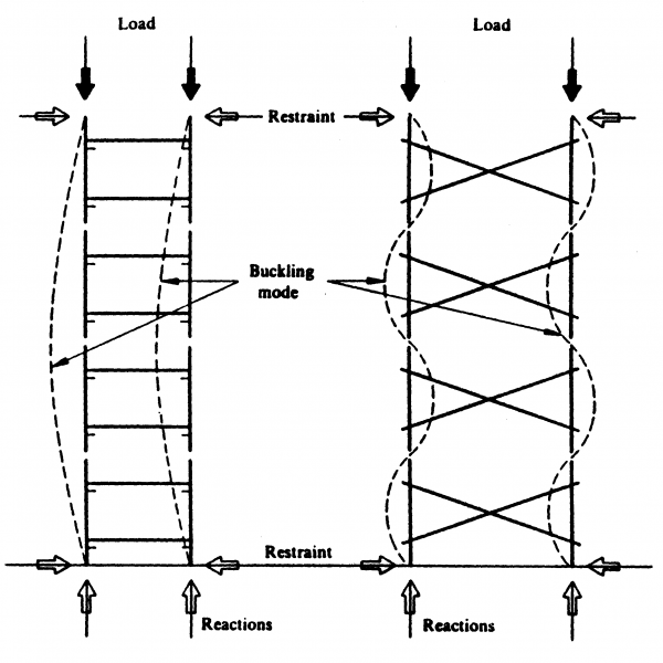
Large shoring towers are typically complex, and require a specific erection sequence prior to application of load. Become familiar with where the shoring towers are restrained. See Figure 1 for typical shoring tower buckling modes:
Formwork
Formwork is defined as a temporary structure or mold used to retain the plastic or fluid concrete in its designated shape until it hardens. Formwork must have enough strength to resist the fluid pressure exerted by plastic concrete and any additional fluid pressure effects generated by vibration.
Forming of the various grades of structural concrete is included in the pay items for the concrete, and is not paid for separately according to the Standard Specifications for construction. There may be special situations in which forming is complex enough to be paid for separately. Check the plans and specifications for formwork pay items, if any.
Formwork is commonly used on MDOT projects for abutments, backwalls, pier columns, pier caps, wing walls, retaining walls, and any other situation where the fluid concrete load must be supported during cure.
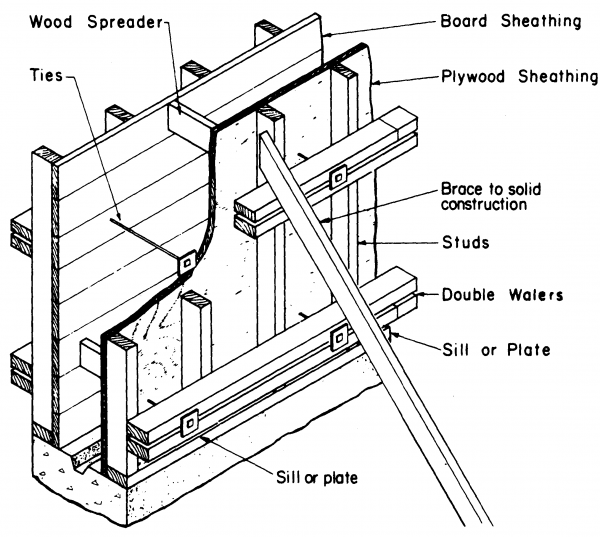
Typical vertical forms consist of the following:
- Sheathing – to provide the design concrete finish
- Studs – to support the sheathing
- Walers – to support the studs and align the forms
- Bracing – to prevent shifting of the forms under construction and wind loading
- Form ties and spreaders – to hold forms a correct spacing under pressure of fluid concrete
See Figure 2 from the Formwork for Concrete (SP-4), Seventh Edition, American Concrete Institute showing the components of vertical forms:
There are several different formwork types depending on the application.
- Job built formwork – consists of a system designed for a specific application, most commonly using plywood and lumber.
- Prefabricated or Modular formwork – A system that has the durability for multiple reuses, and commonly built with plywood with metal framing. These can be built for custom uses on projects.
- Stay-in-Place Formwork – A system designed such that formwork is not removed after construction. These are typically stay-in-place metal deck forms.
Work Platforms and Scaffolding
Work platforms and scaffolding are defined as structural platforms design to support workers, materials and equipment, but are not intended to support the structure being constructed. These platforms can be supported (hung) from the structure, or supported from the ground.
Depending on the complexity of the project, work platforms and scaffolding are typically considered part of the Contractor’s means and methods, and therefore, no separate pay items are included for construction of these items. There may be situations where work platforms will be required due to site access restrictions, or work over waterways. Check the plans and specifications for work platforms or scaffolding pay items, if any.
Temporary Earth Retaining Structures and Cofferdams
There are several types of temporary earth retaining structures, with the predominant type being braced steel sheet piling cofferdams. For information on steel sheet piling and cofferdam design, construction and maintenance please see Section 704 of this manual.
Other types of temporary earth retaining structures include:
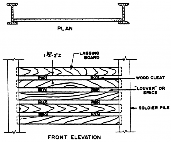
- Soldier Pile Wall – vertical elements (typically steel W or HP shapes) drilled and set with grout or concrete, with lagging (typically timber) spanning the vertical elements to support lateral earth pressures. See Figure 3 below for a typical soldier pile wall layout.
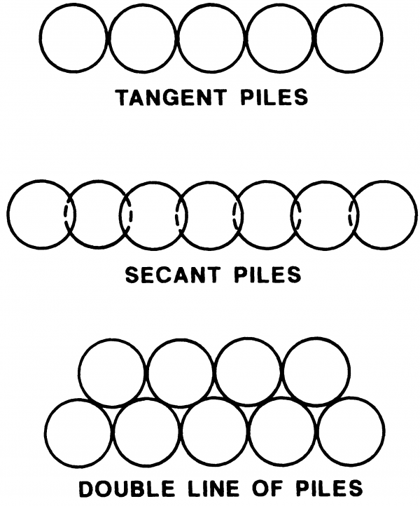
- Tangent or Secant Pile walls – consists of a contiguous row of tangentially touching piles. There are several arrangements of these types of pile walls. See Figure 4 below for pile wall layouts.
- MSE Walls – Mechanically Stabilized Earth (MSE) walls consist of prefabricated walls panels attached to steel reinforcing straps that are embedded in a soil mass. The friction between the straps and the soil mass provides resistance against lateral earth pressures.
- Soil Nail Walls – consist of inserting closely spaced steel bars into the soil mass. Welded wire mesh is extended between and fixed to the protruding portion of the steel bars. The exposed ground surface is then stabilized using shotcrete.
Temporary earth retaining structures (other than Cofferdams) called for on the plans are designed by the bridge designer with input from the Geotechnical Services area. Any Contractor proposed temporary earth retaining structures must be submitted for review and approval per subsection 104.02 of the Standard Specifications for Construction] prior to beginning work.
Design and Approval Process
All temporary works designs are done in accordance with the AASHTO Standard Specification for Highway Bridges, 17th edition, the AASHTO Guide Specifications for Bridge Temporary Works and the specifics as shown in the contract plans and specifications.
Working drawings for temporary works proposed by the Contractor will typically not follow the MDOT plan format, as they are developed by the Contractor. Take the time to review and understand the overall staging scheme, and the sequence of construction for each stage. Once the Contractor’s design is approved, ensure it is built according to the approved design. Any variations, material or section substitutions, or changes in loading or site conditions will require further review by MDOT Bridge Design, Bridge Field Services or the Geotechnical Services area depending on the application.
Become familiar with the working drawings, and take note of the following:
- Design-controlling dimensions
- Beam lengths
- Beam spacing
- Bracing locations
- Connection details
- Welded and bolted joint details
- Access for personnel and equipment
- Erection diagram
- Concrete pour sequences
- Joint locations
- Steel (beams, strands and rods), concrete or timber material grades and stresses
- For modular systems, the method of vertical or horizontal adjustments
MATERIALS
-Reserved-
CONSTRUCTION
Temporary Bridge Structures, Falsework, Work Platforms and Scaffolding
Ensure the Contractor has provided new or used steel or timber materials. Used materials must be in good condition, free of section loss, or other defects. Minor corrosion is acceptable, as most contractors re-use these elements from project to project. Any elements with section loss must be accounted for in the design, and significant section is not permitted, and the element should be rejected. If there are any questions regarding the condition of structural elements to be used, please contact Bridge Field Services for support. Use of used materials must be approved by the Engineer prior to erection.
General certifications are required for steel temporary works materials. Ensure the material grades shown on the plans or working drawing match the material grades of materials brought on site. General certifications can be in the form of manufacturer’s catalog cuts identifying the sections being used.
During temporary bridge structure and falsework erection, ensure the Contractor is providing the proper bracing, and that all vertical members are constructed plumb, with an allowable deviation of 1/8 inch in 3 feet.
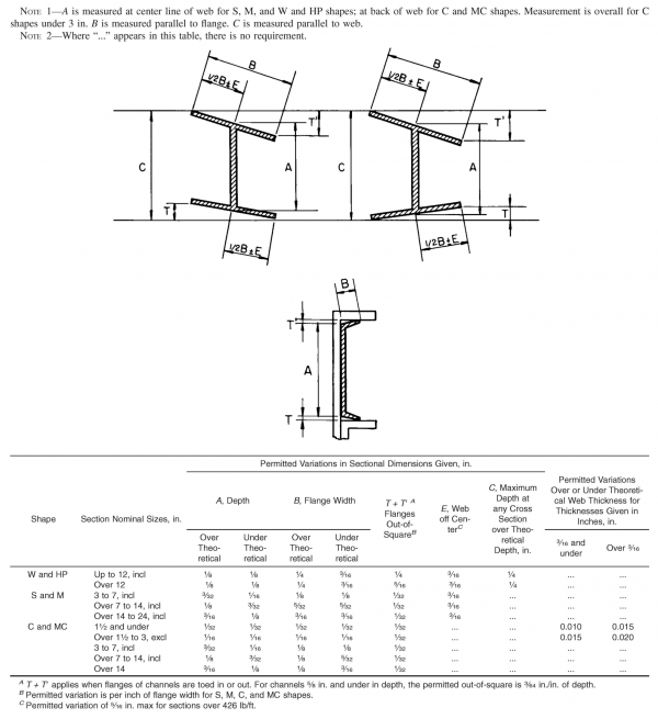
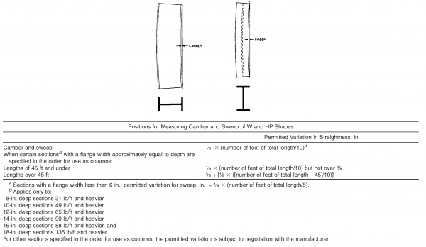
Ensure material section tolerances meet the requirements of “ASTM International “Standard Specification for General Requirements for Rolled Steel Bars, Plates, Shapes, and Sheet Piling for Structural Use (ASTM A6)”. See Figure 5 for permitted variations in sectional dimensions, See Figure 6 for permitted variations in straightness. For welded members, see American Welding Society, Bridge Welding Code, D1.5.
Ensure the Contractor properly maintains temporary bridge structures and falsework during construction operations, and removes these items per subsection 104.07 of the Standard Specifications for Construction.
Ensure both traffic and construction work are protected per section 812 of the Standard Specifications for Construction.]
Check the plans and specifications for temporary traffic control items that are related to temporary works activities.
The following checklist from the AASHTO Construction Handbook for Bridge Temporary Works can be used as a guide for inspection during temporary bridge structure and falsework erection. Some of these elements may not apply to every situation:
- All the working drawings and written instructions have been strictly complied with.
- Only the correct materials in serviceable condition have been employed, especially if specific types or qualities are required.
- The ground has been adequately prepared and steps taken to prevent erosion and settlement.
- Suitable foundation pads or other bases have been provided and have been properly leveled.
- Foundation pads, “sleepers,” and other load-distributing members laid on a slope are adequately prevented from movement down the slope.
- Baseplates have been used and are properly spaced and centered on the supporting foundation pad.
- The extension of each screw or adjustable base is within the permitted limits and braced if necessary.
- Vertical members are plumb.
- Joints in vertical members are properly butted and aligned, and reinforced if required.
- The spacing and level of each lift of bracing members are correct.
- The number and position of all bracing members (longitudinal, lateral, and plan) are correct with connections close to node points.
- Bolted and welded joints are constructed per plan.
Ensure removal of falsework supporting structural concrete elements is not done prior to the concrete attaining 70% of the specified 28-day flexural or compressive design strength, and for at least 5 days following concrete placement per subsection 706.03.O of the Standard Specifications for Construction.
Formwork
Prefabricated or Modular type formwork is typically reused on many different projects. Inspect the formwork when the components arrive on site, and ensure only components that are in good condition are used.
Measure the inside openings of the forms, and compared to plan dimensions for formed elements. Ensure tolerances per subsection 706.03.D of the Standard Specifications for Construction.
The following checklist from the AASHTO Construction Handbook for Bridge Temporary Works can be used as a guide for inspection during temporary bridge structure and falsework erection. Some of these elements may not apply to every situation:
- In addition to inspection prior to concrete placement, inspection should continue during the pour to ensure early recognition of possible form displacement or failure. A supply of extra bracing materials necessary in an emergency should be readily available.
- Construction materials, including concrete, must not be dropped or piled on the formwork in such a way as to damage or overload it.
- Ensure stay in place metal deck forms are welded per plan, or use straps in girder tension zones. Ensure upward pointing legs of the stay in place metal deck form support angles do not encroach into the design thickness of the deck.
- Safe working loads as provided by the manufacturer should never be exceeded. These allowable loads are based on the assumption that the component is in good condition. Products that have excessive thread wear or have been bent, overloaded, or damaged in any way should be discarded or, if possible, reconditioned by the manufacturer. Products from different manufacturers should not be interchanged.
- Any welding of formwork should be performed only by a certified welder. See Section 707 of this manual for details on MDOT certified welders and welders certified by an authorized agency. Extreme caution must be used when field welding in the vicinity of wood forms, as fires have occurred in the forms.
- Improper installation of form ties, including failure to install the required type or number of ties, misalignment of form ties, and incorrect form tie lengths should be avoided.
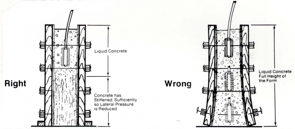
- External vibration should not be used if the forms were not designed for this method of concrete consolidation. Excessive vibration of new concrete or deep vibration into semi-hardened lifts may place higher than expected loads on formwork. Depth of vibration should be limited to the top current lift of new concrete. Also, new concrete should not be placed until previous pours have stiffened sufficiently as to reduce lateral pressures on the forms. See Figure 7 from the Dayton-Superior, Concrete Forming Accessories Product Handbook (06-11):
Temporary Earth Retaining Structures and Cofferdams
For information on steel sheet piling and cofferdam design, construction and maintenance please see Section 704 of this manual.
For other temporary earth retaining structure construction and maintenance, review the plans and specifications, as these items are typically addressed in special provisions.
Removal
Ensure the Contractor removes all bridge temporary works, with the exception of stay in place forms per subsection 104.07 of the Standard Specifications for Construction.
MEASUREMENT AND PAYMENT
-Reserved-
