717 - Downspouts and Drains
GENERAL
The bridge deck drainage system includes the bridge deck, sidewalks, railings, gutters, downspouts, and inlets (or scuppers), referred to as the bridge drain casting assembly. The primary objective of the drainage system is to remove runoff from the bridge deck before it collects in the gutter to a point that exceeds the allowable design spread.
Proper bridge deck drainage provides many benefits:
- Efficiently removing water from the bridge deck enhances public safety by decreasing the risk of hydroplaning.
- The structural integrity of the bridge is preserved, by removing corrosive or otherwise harmful runoff.
- Aesthetics are enhanced (e.g., the avoidance of staining substructure and superstructure members).
- Erosion on the bridge abutment slopes is reduced.
- Settlement of approach slabs is reduced
For proper function, the drainage system must be installed at locations shown on the plans, as the scupper spacing is important for intercepting the calculated flow that meets the allowable water spread criteria. The AASHTO LRFD Bridge Design Specifications 2.6.6.3 specifies the allowable spread of water on the deck. For bridges where the highway design speed is less than or equal to 45 mph, the spread should not encroach on more than one-half the width of any designated traffic lane. For bridges where the highway design speed is greater than 45 mph, the spread should not encroach on any portion of the designated traffic lanes. These items are taken into account during the design phase; however, it is important to understand these requirements, and ensure the Contractor installs all scuppers at the appropriate stationing as shown on the plans. Gutter flow should be intercepted at cross slope transitions to prevent flow across the bridge deck.
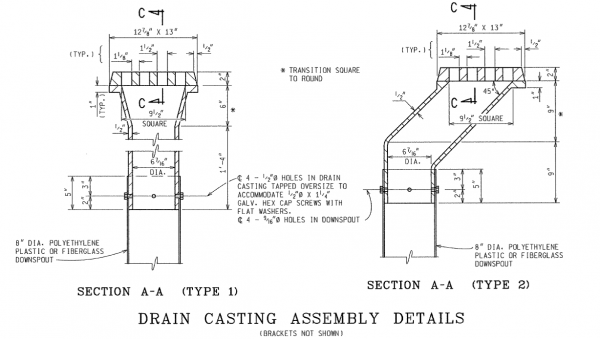
The bridge drain casting assembly is detailed in the Bridge Standard Plan Series B101. Note that the location and placement of the drain casting must be as indicated in the plans. Downspouts must be supported at the intermediate spacing shown on the plans, or closer if field conditions warrant moving a support. Care must be taken to verify the support spacing such that that the downspout deflection remains within allowable tolerances.
Alternate drain casting or down spout assemblies and materials may also be used, and will be detailed in the plans and specifications. Call Bridge Field Services with any questions regarding drain casting assemblies or materials.
MATERIALS
Bridge deck downspouts can be polyethylene (PE) pipe Schedule 40 (specifically ASTM D2447, PE 3406), or fiberglass reinforced thermosetting resin pipe (RTRP), in accordance with subsection 909.08 of the Standard Specifications for Construction. The drain casting assembly as detailed in [[Bridge deck downspouts can be polyethylene (PE) pipe Schedule 40 (specifically ASTM D2447, PE 3406), or fiberglass reinforced thermosetting resin pipe (RTRP), in accordance with subsection 909.08 of the Standard Specifications for Construction.|bridge standard plans B101]] consists of a slotted grey cast iron grate, with a transition coupler to facilitate attachment of circular pipe. Ensure all drain castings and miscellaneous metal materials are in accordance with subsection 908 of the Standard Specifications for Construction. See Figure 1.
CONSTRUCTION
-Reserved-
MEASUREMENT AND PAYMENT
-Reserved-
