Difference between revisions of "802 - Concrete Curb, Gutter, and Dividers"
| Line 182: | Line 182: | ||
[[Category:Construction Manual]] | [[Category:Construction Manual]] | ||
| + | [[Category: Division 8]] | ||
| + | [[Category: Section 802]] | ||
Revision as of 17:14, 12 May 2021
GENERAL
Three methods are in general use to construct curb or curb and gutter slipformed, fixed forms and integral curb. See the Standard Plan R-28 through R-31 Series and review plans for sidewalk, ramp and drive opening locations.
When slipforming curb, detail “M” returns are best omitted by placing bulkheads at each spring point. Returns are normally cast later as a separate operation.
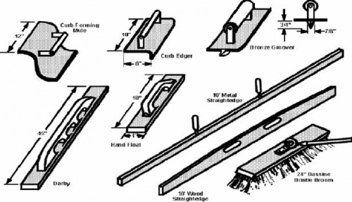
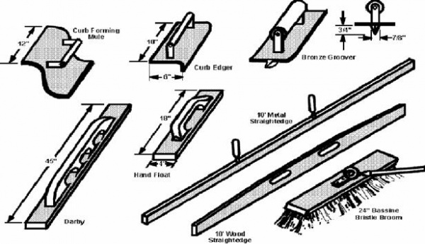
Curb returns at intersections are also cast separately. For this work a curb forming mule matching the curb face should be used. See Figure 802-1.
MATERIALS
-Reserved-
CONSTRUCTION
Projects with large amounts of curb and gutter will almost always be constructed by the slipform method. Slipform machines either are track or wheel mounted. The base on which the curb is placed and the machine rides must be trimmed to the proper grade and compacted. This operation is usually performed by a separate curb form grader, or occasionally the same machine used to place the concrete.
Slipform
Line and grade control may be taken from the edge of the pavement. If not, a string line must be erected behind the curb for line and grade control, for trimming grade and for elevation control of the back of the curb. For short radius curves, the stakes supporting the string line may have to be placed as close together as 10 foot (3 m) to ensure a smooth curve. The string line should be visually checked to determine that it is free of vertical or horizontal irregularities.
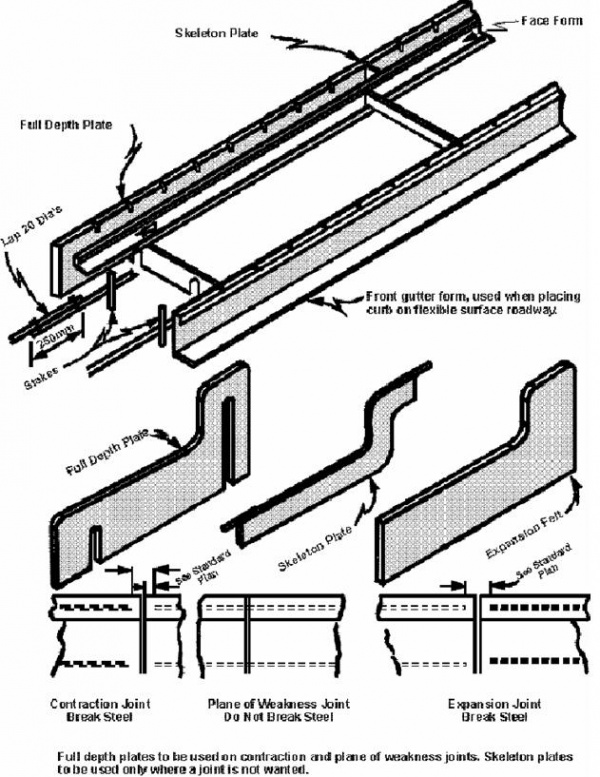
Since curbs and gutters are usually reinforced, provisions must be made for positioning the steel. The usual procedure is to spread the steel on the prepared base in front of the placing operation. The steel is to be lapped and tied together, as specified in Section 802 of the Standard Specifications for Construction (also see Figure 802-3). When a curb is placed adjacent to a concrete pavement or base course, the gutter and pavement will be tied together with lane ties. These lane ties can be used to support one of the longitudinal reinforcing bars. The other bar or bars are usually fed into the front of the machine as the concrete is extruded from the slipformer.
The steel will need to be gapped on each side of each expansion and contraction joint, but continued through any plane-of-weakness joints.
Before slipforming starts, the screed or mule that forms the curb should be checked to see that it conforms to the detail specified.
A low slump concrete 1/8 inch (about 2 mm) will be needed for proper slipforming. Only an occasional slump test will be required, since it is almost impossible to slipform with concrete exceeding the 3 inch (75 mm) slump limit. However, frequent air content tests should be made, as entraining the specified air in a low slump mix is sometimes difficult. If truck mixers are used, a supply of air entraining agent should be available on the job site to correct loads of concrete with low air content.
All slipform machines use internal vibrators to consolidate and mold the concrete to the required cross section. Malfunction of one or more vibrators will cause tearing or honeycomb in the concrete behind the machine.
As the curb is extruded behind the machine, the inspector should check the cross section for conformance with the Standard Plan R-30 Series. Be sure to check for proper gutter drops with a carpenter’s level and a ruler.
Also, check the back and face of the curb for honeycomb or other imperfections. The Contractor’s workers should use a 10 foot (3 m) straightedge along the top, gutter pan and face of the curb to check for irregularities. Any variation exceeding 3/16 inch in 10 foot (5.0 mm in 3 m) in the gutter or top of the curb is to be corrected before the concrete sets. For the balance of the curb, a tolerance of 3/8 inch in 10 foot (10 mm in 3 m) is permitted. If the slipform machine is functioning properly, only minor corrective work should have to be done by the finishers.
Plane-of-weakness joints are not required in curbs.
Fixed Form
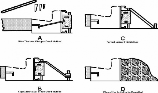
If fixed forms are to be used, the forms must be set to line and grade and braced to withstand the force of the concrete against them. A string line is needed for proper form alignment. Acceptable bracing is shown in Figure 802-2. Forms are to be full depth at the back of the curb.
Reinforcement should be supported in position by metal stakes before concrete is deposited.
Face forms are supported from the back form by use of division plates. See Figure 802-3. In addition to supporting the face forms, these plates form a plane-of-weakness joint in the curb. All forms and plates should receive a coat of oil to prevent concrete bonding to them. Oil should be kept off the reinforcing steel.
Face forms are removed after the concrete starts to set and finishing is completed as described for a slipformed curb. The back of the curb must be coated with curing compound after forms are removed.
Joints
Installation of expansion joints is an item that needs the inspector’s attention. Review Standard Plan R-30 Series for location of these joints. Usually they are installed behind the slipform machine, by removing the concrete from the joint area with a narrow shovel or trowel. The 1 inch (25 mm) expansion material is then placed in position and the concrete replaced against the expansion material. Check to see that the expansion material is the proper shape to fit the proposed curb and that it is placed snugly against the adjacent pavement. Any damaged expansion material should be rejected. The concrete should be rodded or spaded to consolidate it against the expansion material and to bond the replaced concrete into the adjacent concrete. The joint should be finished by straightedging across it and edging along the top of the expansion material. No concrete should be left bridging the expansion joint material.
Contraction joints can be formed or sawed into the curb behind the placing operation. The depth must be at least 3 of the gutter thickness. Normally, they are formed with a groover (see Figure 802-1). As the groover lip is only about 3/4 inch (20 mm) long, a trowel should be forced down into the center of the groove to separate the concrete to a depth of 2.5 inches (65 mm) or more.
Expansion joints in a fixed form curb are staked ahead of concrete placement. Care should be used in placing concrete on each side of the joint material. This area should be vibrated to ensure proper consolidation.
Finishing and Curing
Finally, the top of the curb at the back corner and the front edge adjacent to the pavement should be rounded with a curb edger (Figure 802-1).
Following finishing, the exposed portion should be textured with a burlap drag or a broom to provide a uniform appearance. On freestanding curbs, plan stationing shall be stenciled in the top of the curb.
When all free moisture has disappeared, the curb should be coated with white membrane curing compound at a rate of 1 gallon per 25 square yards (1 liter per 5 m5). As measuring the application rate is difficult, make sure the entire surface, including the back and front lip adjacent to the base course, is completely coated so that the moisture in the concrete is sealed in.
Miscellaneous Curb and Gutter
Valley gutters and rolled curb joints will require sealing if adjacent to a neoprene-sealed pavement. Barrier curb joints normally will not be sealed. The longitudinal joint between pavement and gutter must be sawed and sealed. Details of this joint are shown on the Standard Plan R-41 Series.
An integral curb does not require lane ties between pavement and gutter or sawing and sealing of this joint.
A curb is sometimes repaired by use of "curb cap". Broken sections of the standing part of the curb are removed down to approximately the gutter line. Then, a new straight curb is cast over the old curb base. Dowel bars are required on shorter sections. Special details will be included in the plans or proposal for this work.
Checklist for Inspection
|
|
|
|---|---|
|
Base |
Compacted to 95 percent of Maximum Unit Weight. |
|
Line and Grade |
Check before the start of placement and periodically during placement using a level and ruler. |
|
Forms |
Check profile, placement and preparation of forms, screeds and mules. Forms are to be back braced to resist concrete pressure. Individual sections of curb should be at least 8 inches (200 mm) in length. |
|
Reinforcement |
Check for correct size and placement. Reinforcement shall not be carried through expansion or contraction joints. A good rule of thumb to remember is that steel is to be broken in curb whenever it is broken in the abutting pavement. Reinforcement shall be lapped 10 inches (250 mm) and tied. |
|
Slump and Air |
Test as required in Division 6 of this manual. |
|
Cross Section |
Check periodically for conformance to plans. |
|
Slipforming |
Check for tearing or honeycomb of slipform concrete. |
|
Joints |
Placement and installation are extremely important. Curb joints should match expansion, contraction and plane-of-weakness joints in concrete pavement or base course. Curbs not tied to concrete pavement or base course should have expansion joints at approximately 400 feet (120 m) intervals or at street returns, whichever is closer. |
|
Finishing |
Finished edges and textured surface are required. Finished surfaces shall be straightedged with a 10 foot (3 m) straightedge lapped at 3 feet (1 m). Gutter and top of curb shall not vary more than 3/16 inch in 10 feet (5 mm in 3 m). All edges and joints to be rounded with a 1/4 inch (6 mm) radius tool. Finish with a light brush, broom or burlap. Honeycomb areas are to be patched with mortar after removal of forms. If excessive, vibrator is to be used on future work. |
|
Curing |
Curing compound applied at 1 gallon per 25 square yards (1 liter per 5 m2). Curing is to be accomplished as for concrete pavement. Back of curb to be cured with membrane. On independent curb, the front as well as the back of curb shall be cured even though a HMA surface roadway abuts it. |
|
Backfill |
Backfill as soon as concrete has gained sufficient strength. Particular attention should be paid to backfilling adjacent to back of curb to minimize settlement at a later date. |
|
Catch Basin |
Catch basin casting should be 1 inch (25 mm) lower than plan grade to ensure that no water is ponding in gutter. In flat areas, gutter should be water tested after final finish is completed. Bolts on side and back of casting should be tightened to support mail box portion of casting. |
MEASUREMENT AND PAYMENT
-Reserved-


