Difference between revisions of "810 - Permanent Traffic Signs and Supports"
| (40 intermediate revisions by 2 users not shown) | |||
| Line 4: | Line 4: | ||
<center><span STYLE="font: 40pt arial;">'''Permanent Traffic Signs and Supports'''</span></center> | <center><span STYLE="font: 40pt arial;">'''Permanent Traffic Signs and Supports'''</span></center> | ||
| − | |||
| − | ==[[#GENERAL|GENERAL]]== | + | ==[[#GENERAL DESCRIPTION|GENERAL DESCRIPTION]]== |
| − | + | Roadway signage is a critical safety feature and construction staff should ensure all signage is properly constructed & installed correctly in the proper location. Misplaced or irregular signs can create a critical hazard to traffic. | |
| + | |||
| + | Modern signs/supports can be quite large and will require close cooperation between all forces on highway construction projects so the roadway is signed properly when opened to traffic. | ||
| + | |||
| + | Any sign that is erected on a section of roadway not immediately applicable to traffic shall be covered in accordance with Standard Specifications for Construction Sections 812.03.D and 922.02.D until the appropriate time for uncovering it. It is essential that signs with conflicting messages not be displayed. | ||
| + | |||
| + | ==[[#MATERIALS|MATERIALS]]== | ||
| + | |||
| + | All materials for installation on permanent signing projects must meet the requirements | ||
| + | of the MDOT Sign Support Standards and in accordance with Section 919 of the Standard | ||
| + | Specifications for Construction. | ||
| + | |||
| + | Materials incorporated into MDOT signing projects which are not listed on the Qualified Product List must be accounted for by the Engineer who completes and submit a Materials Source list form to initiate appropriate action for basis of acceptance. This form shall be complete and cover all materials which are identified on the plans or in the specifications. The Materials source list and documentations shall be in accordance to the Materials Source Guide and supplemental Manuals. | ||
| + | |||
| + | |||
| + | ==[[#EQUIPMENT|EQUIPMENT]]== | ||
| + | |||
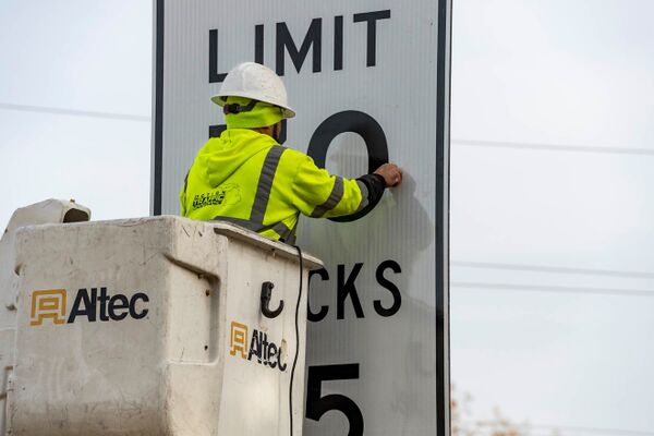
| + | A large selection of tools, supplies and heavy machinery are necessary for the installation of ground mounted and overhead signs and their supports. Below are a just a few examples of items that may be applicable for construction of permanent signing projects. | ||
| + | |||
| + | === Trucks/Machinery === | ||
| + | * Truck mounted Cranes, Augers & Hydraulic Post drivers | ||
| + | * Truck mounted booms | ||
| + | * Light towers (for nighttime installation activities) | ||
| + | * Backhoe | ||
| + | |||
| + | [[File:810a.jpg|600px|thumb|center|'''Truck with Crane and Auger Pulling Sign Trailer''']] | ||
| + | |||
| + | |||
| + | |||
| + | [[File:810b.jpg|600px|thumb|center|'''Truck Crane using Nylon Lifting Strap to Lift Sign''']] | ||
| + | |||
| + | |||
| + | |||
| + | [[File:810c.jpg|600px|thumb|center|'''Truck Mounted Boom Box''']] | ||
| + | |||
| + | |||
| + | |||
| + | [[File:810d.jpg|600px|thumb|center|'''Boom Box Lift for Contractor to Work on Sign (Note Arrow Board)''']] | ||
| + | |||
| + | |||
| + | |||
| + | [[File:810e.jpg|600px|thumb|center|'''Boom Box Lift & Truck Mounted Crane with Auger Installing Ground Mount Sign''']] | ||
| + | |||
| + | |||
| + | |||
| + | [[File:810f.jpg|600px|thumb|center|'''Truck Mounted Attenuator (TMA)''']] | ||
| + | |||
| + | |||
| + | |||
| + | === Survey === | ||
| + | * Lasers & Levels (4 foot levels for checking plumb of Posts and/or Uprights) | ||
| + | * Stakes, Flagging tape, marking utensils | ||
| + | * Upside-down paint (for staking/marking posts) | ||
| + | * Survey Rods | ||
| + | * Transit levels | ||
| + | |||
| + | === Tools === | ||
| + | * Concrete finishing tools: Used to mold and shape post foundations after pour | ||
| + | * Sawzalls: Used( for cutting off old Wood posts near it’s foundation | ||
| + | * Sledgehammers | ||
| + | * Torch cutters: Used for cutting off anchor rod/bolts of End supports from concrete bases | ||
| + | * Torque wrench, Hydraulic wrench, hand wrench | ||
| + | * Torque Drills, Drill bits & Hex Sockets | ||
| + | * Air Compressors, Air Hammers | ||
| + | * Angle Grinders | ||
| + | * Post Hole Concrete core drills & cutters | ||
| + | |||
| + | [[File:810g.jpg|600px|thumb|center|'''Contractor using a Torque Drill to Tighten the Nut. (Always Tighten the Nut, not the Bolt Head)''']] | ||
| + | |||
| + | |||
| + | |||
| + | |||
| + | [[File:810i.jpg|600px|thumb|center|'''Hand Wrenches Used to Snug Fit the Nut on Anchor Bolt''']] | ||
| + | |||
| + | === Measuring Devices === | ||
| + | * Measuring Tapes | ||
| + | * Measuring Wheels | ||
| + | * Carpenters folding ruler: Used for measuring sign dimensions, base plate standoff. | ||
| + | * Laser Distance Measuring tool: Used for measuring Clearances and Span Lengths | ||
| + | |||
| + | |||
| + | [[File:810j.jpg|600px|thumb|center|'''Contractor Using a Tape Measure to Layout Holes for Drilling''']] | ||
| + | |||
| + | |||
| + | === Miscellaneous === | ||
| + | * Nylon straps, slings and hooks | ||
| + | * Sand bags | ||
| + | * Stencils for Sign Support Structure ID’s on uprights | ||
| + | * Spray paint: Used for painting structure numbers to vertical supports/poles of structures. | ||
| + | * Calipers: Used for measuring diameter or thickness of smaller structure components such as anchor bolts, base plate connections or component section losses. | ||
| + | |||
| + | |||
| + | |||
| + | [[File:810h.jpg|600px|thumb|center|'''Black Paint Stenciled Structure Number on Upright''']] | ||
| + | |||
| + | |||
| + | |||
| + | |||
| + | Work safety during use of equipment and tools is of the utmost importance in signing projects. The Contractor must agree to provide the labor and supervision machinery, tools, apparatus and other means of construction; do all the work in manner of safety for their crews and the motorist; furnish all necessary resources and take any steps as may be needed to complete project in strict accordance with contract plans and the proposal to the satisfaction of the Department. | ||
{{top}} | {{top}} | ||
| − | ==[[# | + | ==[[#PRECONSTRUCTION|PRECONSTRUCTION]]== |
| + | |||
| + | ===[[#SUBMITTALS|SUBMITTALS]]=== | ||
| + | ==== Contract Award Information ==== | ||
| + | :Contractor may view the status of award at the “Construction Contract Inquiry” site. Questions not answered there should be directed to [mailto:Change?to=MDOT-awards@michigan.gov MDOT-awards@michigan.gov] | ||
| + | |||
| + | ==== Contractor DBE Commitment ==== | ||
| + | :Submit MDOT Form 2653 and any questions to [mailto:Change?to=MDOT-DBESheets@michigan.gov MDOT-DBESheets@michigan.gov] | ||
| + | |||
| + | ==== Insurance Requirements ==== | ||
| + | :Contractors will submit their insurance documents directly to ProjectWise by dropping the insurance document in the INSURANCE folder found under the Awards folder. | ||
| + | |||
| + | ===[[#SHOP DRAWINGS|SHOPDRAWINGS]]=== | ||
| + | Working drawings of sign support structures shall be reviewed by the Project Engineer for conformance with the Standard Plans and contract requirements. The Project Engineer approves shop drawings in conformance with the standard plans. Any request to deviate from standard plans should be reviewed by the MDOT Bridge and Structures office in compliance with Structural Fabrication Quality Manual. | ||
| + | |||
| + | The working drawings of special design sign structures and/or special sign fittings shall be submitted to the MDOT Bridge and Structures office, which will coordinate approval | ||
| + | with the Structural Fabrication Unit. After approval, the MDOT Bridge and Structures office will retain one set and forward the approved PDF file to the Project Office. The | ||
| + | Project Engineer will forward the approved PDF file to the Contractor, who will forward to the Fabricator. | ||
| + | |||
| + | Fabrication should proceed only with approved shop drawings. However, if the Fabricator must proceed prior to receipt of approved shop drawings (performing work at their own risk), ensure that the Structural Fabrication Unit is aware of this activity and await instructions on how to proceed. If the Project Engineer permits the work to proceed without approved shop drawings, proceed with basic Quality Assurance functions using the non-approved shop drawings in accordance with the Structural Fabrication Quality Manual. Later, verify notes against the approved drawings. Notify the Structural Fabrication Unit immediately if fabrication is not in conformance with the approved shop drawings. | ||
| + | |||
| + | |||
| + | If a structural review is not required by the MDOT Bridge and Structures office, the Project Engineer shall initiate MDOT’s two-part acceptance process for structural products to be accepted in accordance with Section 1.1.7 of the Structural Fabrication Quality Manual. | ||
| + | |||
| + | All drawings shall be clearly marked before returned to the Contractor, whether reviewed and checked by the Project Engineer or the MDOT Bridge and Structures Office. The Project Engineer is responsible for checking the geometric features of these items. Specific items that should be checked include the following: | ||
| + | * Foundation Location | ||
| + | * Bridge Beam fascia’s | ||
| + | * Concrete Barrier locations | ||
| + | |||
| − | + | The special provisions of the contract deal to a great extent with the proper fabrication | |
| + | of the signs to be installed and the manufacturing process requiring the use of approved | ||
| + | materials and application equipment. It is necessary, therefore, that the sign manufacturer who actually makes the signs be approved as a source of supply with certifications that meets all MDOT listed specifications requirements in accordance with Materials Source Guide. | ||
{{top}} | {{top}} | ||
==[[#CONSTRUCTION|CONSTRUCTION]]== | ==[[#CONSTRUCTION|CONSTRUCTION]]== | ||
| + | |||
| + | === Location of Signs === | ||
| + | |||
| + | Since it is impossible to visualize the actual physical features of final grade elevations, vertical curves, trees, and other factors that affect proper sign placement in the initial | ||
| + | development of signing plans, it becomes necessary to make adjustments in sign location just prior to installation. The Project Designer and Traffic Engineer should coordinate a study of each location to determine that each sign will be in the most efficient location for visibility and nighttime reflectivity. Groundmount signs may be moved up to 50 ft in either direction if severe ground, slope conditions or utilities are encountered, and constructability becomes issue. If an Advance guide sign must be moved more than 800 ft, consideration should be given to checking the distance mileage on the sign and keeping to the nearest 1 mile. In some cases, a ½ Mile sign may be necessary where location for a 1 mile is not feasible. New sign locations must be determined by Project Engineer shall be staked by the Engineer prior to installation by the Contractor. | ||
| + | |||
| + | For staking of the signs, the contractor may opt to use paint lines on existing sign supports for the inspection and final measurement of the work as called for on plans. | ||
| + | |||
| + | === Sign Support Structure Identification Information === | ||
| + | |||
| + | Anytime an existing cantilever, or a Truss sign structure is replaced or removed from service, the Contractor shall remove the existing sign structure in accordance with Subsection 810.03.U of the Standard Specifications for Construction. The Project Engineer will complete [https://mdotjboss.state.mi.us/webforms/GetDocument.htm?fileName=0467.pdf form 0467] of this work and submit it to MDOT Operation Field Service office so the sign support structure can be updated in the inventory system. | ||
| + | |||
| + | === Sign Posts, Bridge Sign Connections and Sign Support Structures === | ||
| + | |||
| + | It is important to ensure the proper torque is applied to anchor bolts connecting the bases when installing Standard Plan SIGN-300 series from MDOT’s Sign Support Standards. Procedures for assembling and inspecting high strength bolts are covered in FUSP 20SP-810H and [https://mdotwiki.state.mi.us/images_construction/9/95/2020-Standard-Specifications-Construction.pdf#page607 Section 810.03] of the Standard Specifications for Construction. All base assemblies shall be checked with a torque wrench to ensure proper snug tightness of the top nut. This can be accomplished either by observing the Contractor’s torquing or by the Inspector initiating an Anchor Bolt testing with a torque wrench. Documentation of the torquing method used should be accomplished by proper entries in the Inspector’s Daily Reports. | ||
| + | |||
| + | |||
| + | |||
| + | {{top}} | ||
| + | |||
| + | ==[[#INSPECTION & TESTING|INSPECTION & TESTING]]== | ||
| + | |||
| + | === Inspections === | ||
| + | There are several types of inspections depending on the circumstance of the signing contract. These inspections follow those typically performed for Road, Bridge and Ancillary Structures inspections. The Michigan Ancillary Structures Inspection Manual (MiASIM) outlines procedures for performing in-service inspections of ancillary structures including, but not limited to sign support structures, DMS support structures, ESS towers, lighting towers, steel strain poles, sign trusses, wood poles, frangible lights, non-frangible lights, and mast arms. | ||
| + | |||
| + | ==== Initial Inspection ==== | ||
| + | This inspection should be performed shortly after an asset is constructed or installed. It is important to ensure anchor bolts are tightened properly and that an asset does not have any deficiencies or damage. Anchor bolts should be pretensioned in accordance with the turn-of-nut method in FUSP 20SP-810H. Anchor bolts can become loose and must be inspected in accordance with FUSP 20SP-810A. All materials furnished from the contractor additionally must be in accordance with the Standard Specification for Construction. See FUSP 20SP-810A for procedures related to requesting this inspection and contact the Ancillary Structures Unit at MDOT-Ancillary@michigan.gov with any questions. This includes those assets listed below: | ||
| + | |||
| + | * Cantilever, Type E | ||
| + | * Cantilever, Type J | ||
| + | * DMS Support Structures | ||
| + | * ESS Towers | ||
| + | * Frangible Light Pole Structures | ||
| + | * Non-Frangible Light Pole Structures | ||
| + | * Tower Lighting Structures | ||
| + | * Mast Arm Support Structures | ||
| + | * Truss, Type C & D | ||
| + | * Truss, Type E | ||
| + | * Steel Strain Poles | ||
| + | |||
| + | ==== Routine Inspection ==== | ||
| + | This can simply consist of a ground level inspection with no lane closures. Ground-mounted signs and their post supports are inspected for missing lock washers, bolts and any fastening hardware as required per Standard sign support drawings. Sign sheeting should be inspected for tears, excessive wrinkles or twisting of sheeting behind bolt heads. The spacing distance between 2 posts for one sign and it’s bottom height should be in accordance to the Standard Sign Support drawings. A installation date sticker should be checked for as applied by contractor on the back of a permanent sign. | ||
| + | |||
| + | For Inventory of Sign Support Structures, routine inspection program is recommended to obtain the structure information and quickly look for any deficiencies in and around base plates and foundations. Verify Sign Support structure Upright is Stenciled with it’s ID in accordance with the plans and Standard Specifications for Construction. A Punch list is a document created by the Department personnel or it’s representing inspectors generated from this inspection type near the projects close-out. It’s imperative to perform this inspection in a timely manner to allow time for contractor and his crews to follow upon. | ||
| + | |||
| + | ==== Final Inspection ==== | ||
| + | This would be an activity by the inspector if a sign, sign support structure or post is found to have deficiencies or other materials issues as noted from a Punch list that require more frequent inspection than the typical inspection frequency to ensure compliance with Standards and Departments satisfaction. This inspection generally follows up on with repairs, fixes and/or corrections as noted from the Punch list. | ||
| + | |||
| + | |||
| + | |||
| + | === Inspection Tools === | ||
| + | The list below is what would be considered common tools for the construction engineer and/or inspector during construction of a signing project. | ||
| + | |||
| + | * 4-foot Level: Used for checking plumbness of non-tapered vertical supports/poles and checking levelness of other components. | ||
| + | * Plumb Bob: Used for checking tapered and non-tapered vertical support/pole plumbness and bowing. | ||
| + | * Nylon string: Used for determining and measuring sag or any other distortion to a chord or other member. | ||
| + | * Laser Distance Measuring Tool: Used to measure clearances and span lengths. | ||
| + | * 25-foot Steel Tape Measure: Used for measuring sign dimensions, anchor bolt diameters, base plate standoff distances, and deficiency sizes, etc. | ||
| + | * Folding Ruler: Used for measuring some sign dimensions, anchor bolt diameters, base plate standoff distances, deficiency sizes, and used as a scale in photographs. | ||
| + | * Calipers: Used for measuring diameter or thickness of smaller structure components, such as anchor bolts, and component section losses. | ||
| + | * Crack Gauge: Used for measuring width of cracks. | ||
| + | * Feeler or Taper Gauge: Used for measuring gaps between parts or pieces such as gaps between top nuts and base plates. | ||
| + | * D-meter: Used for measuring thickness of components where access to one side is restricted (e.g., pole wall thickness). | ||
| + | * 8-foot Aluminum Range Pole: Used in prodding for scour around culvert and for placing in photos to help show depth of scour or embankment erosion | ||
| + | |||
| + | |||
| + | Construction personnel or it’s representative should be fully equipped to perform basic inspection activities of permanent signing projects. Additional equipment or tools may be needed as circumstances warrant to ensure a complete and thorough inspection for Quality Assurance. | ||
| + | These types of Inspections are for In-service construction contracts for permanent signing projects. | ||
| + | |||
| + | Other area programs conduct inspections for Sign Support Structure preservation, monitoring and inventory purposes. Refer to the Michigan Ancillary Structures Inspection Manual (MiASIM) that provides general operational guidelines as well as Inspector qualifications. | ||
| + | |||
| + | === Installation Date Sticker === | ||
| + | An installation date sticker must be hole-punched by the sign contractor and shall be attached on the back of all permanent signs that are received on the project. Signs without such indicated acceptance shall not be permitted on the project. Damaged signs shall be rejected. | ||
| + | |||
| + | At the completion of a signing project, the Project Engineer shall request appropriate personnel to assist in making a final inspection for a punch list to be addressed by Contractor. | ||
| + | |||
| + | === Inspection Issue Example Photographs === | ||
| + | |||
| + | [[File:810-1.jpg|600px|thumb|center|'''Failure at the Weld Root for Connecting Cross Members''']] | ||
| + | |||
| + | |||
| + | |||
| + | |||
| + | [[File:810-2.jpg|600px|thumb|center|'''Structure Support Member Split After Impact''']] | ||
| + | |||
| + | |||
| + | |||
| + | |||
| + | [[File:810-3.jpg|600px|thumb|center|'''Upright Damaged by Impact and Top of Foundation/Base Plate Buried''']] | ||
| + | |||
| + | |||
| + | |||
| + | |||
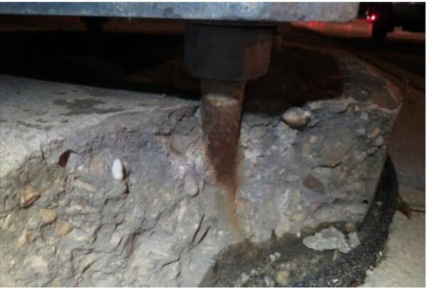
| + | [[File:810-4.jpg|600px|thumb|center|'''Concrete Pad Deteriorating and Exposing Anchor Rod/Leveling Nut''']] | ||
| + | |||
| + | |||
| + | |||
| + | |||
| + | [[File:810-5.jpg|600px|thumb|center|'''Complete Weld Failure''']] | ||
| + | |||
| + | |||
| + | |||
| + | |||
| + | [[File:810-6.jpg|600px|thumb|center|'''Signs Removed by Contractor. The White Paint on the post indicates a “Staked” item per contract. Pink paint on top of white paint indicates that new post holes are augered out and ready for fresh concrete pour.''']] | ||
| + | |||
| + | |||
| + | |||
| + | |||
| + | [[File:810-7.jpg|600px|thumb|center|'''High Load Impact Damage to Bottom Portion of Overhead Sign''']] | ||
| + | |||
| + | |||
| + | |||
| + | |||
| + | [[File:810-8.jpg|600px|thumb|center|'''Sign Cover Fully Contacting the Sign Reflective Surface with Rivets''']] | ||
| + | |||
| + | |||
| + | |||
| + | |||
| + | [[File:810-9.jpg|600px|thumb|center|'''Rivets Penetrating the Substrate of Sign''']] | ||
| + | |||
| + | |||
| + | |||
| + | |||
| + | [[File:810-10.jpg|600px|thumb|center|'''Drilled Shaft Bore Hole Covered After Utility Impacts''']] | ||
| + | |||
| + | |||
| + | |||
| + | |||
| + | [[File:810-11.jpg|600px|thumb|center|'''Member Failure Due to Excessive Vibration and Lack of Galvanization Coating.''']] | ||
| + | |||
| + | |||
| + | |||
| + | |||
| + | [[File:810-12.jpg|600px|thumb|center|'''Section Loss of Concrete Pad and Corrosion of the Anchor Bolt''']] | ||
| + | |||
| + | |||
| + | |||
| + | |||
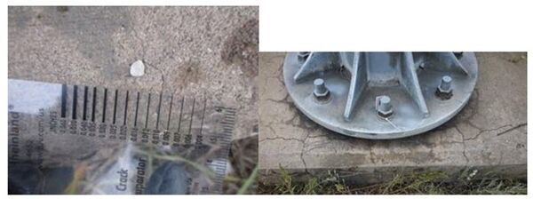
| + | [[File:810-13.jpg|600px|thumb|center|'''Stress Fractures and Cracks in Older Foundations.''']] | ||
| + | |||
| + | |||
| + | |||
| + | |||
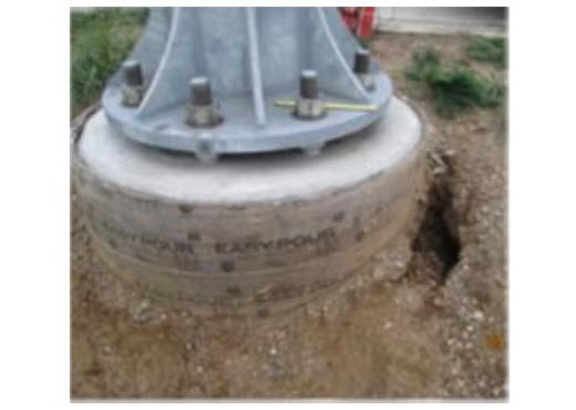
| + | [[File:810-14.jpg|600px|thumb|center|'''Soil Erosion Around New Foundation from Poor Turf Establishment''']] | ||
| + | |||
| + | |||
| + | |||
| + | |||
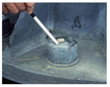
| + | [[File:810-15.jpg|600px|thumb|center|'''Anchor Bolt Nut Not Fully Engaged Past Minimum Thread Count''']] | ||
| + | |||
| + | |||
| + | |||
| + | |||
| + | [[File:810-16.jpg|600px|thumb|center|'''Galvanizing Damaged Observed During Initial Inspection''']] | ||
| + | |||
| + | |||
| + | |||
| + | |||
| + | [[File:810-17.jpg|600px|thumb|center|'''Missing Flat Washer Under the Hex Head Bolt''']] | ||
| + | |||
| + | |||
| + | |||
| + | |||
| + | [[File:810-18.jpg|600px|thumb|center|'''Lock Washer Not Fully Compressed Under the Nut''']] | ||
| + | |||
| + | ==[[#MEASUREMENT, DOCMENTATION & PAYMENT|MEASUREMENT, DOCMENTATION & PAYMENT]]== | ||
<span style="color: red"> -Reserved- </span> | <span style="color: red"> -Reserved- </span> | ||
| − | |||
| − | ==[[# | + | ==[[#LOCAL AGENCY PROJECT CONSIDERATIONS|LOCAL AGENCY PROJECT CONSIDERATIONS]]== |
| + | |||
| + | <span style="color: red"> -Reserved- </span> | ||
| + | |||
| + | ==[[#RAIL PROJECT CONSIDERATIONS|RAIL PROJECT CONSIDERATIONS]]== | ||
<span style="color: red"> -Reserved- </span> | <span style="color: red"> -Reserved- </span> | ||
| + | |||
| + | |||
{{top}} | {{top}} | ||
[[Category:Construction Manual]] | [[Category:Construction Manual]] | ||
| + | [[Category: Division 8]] | ||
| + | [[Category: Section 810]] | ||
| + | [[Category:New CM Format]] | ||
Latest revision as of 15:38, 2 April 2024
GENERAL DESCRIPTION
Roadway signage is a critical safety feature and construction staff should ensure all signage is properly constructed & installed correctly in the proper location. Misplaced or irregular signs can create a critical hazard to traffic.
Modern signs/supports can be quite large and will require close cooperation between all forces on highway construction projects so the roadway is signed properly when opened to traffic.
Any sign that is erected on a section of roadway not immediately applicable to traffic shall be covered in accordance with Standard Specifications for Construction Sections 812.03.D and 922.02.D until the appropriate time for uncovering it. It is essential that signs with conflicting messages not be displayed.
MATERIALS
All materials for installation on permanent signing projects must meet the requirements of the MDOT Sign Support Standards and in accordance with Section 919 of the Standard Specifications for Construction.
Materials incorporated into MDOT signing projects which are not listed on the Qualified Product List must be accounted for by the Engineer who completes and submit a Materials Source list form to initiate appropriate action for basis of acceptance. This form shall be complete and cover all materials which are identified on the plans or in the specifications. The Materials source list and documentations shall be in accordance to the Materials Source Guide and supplemental Manuals.
EQUIPMENT
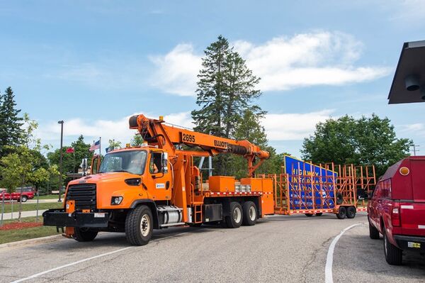
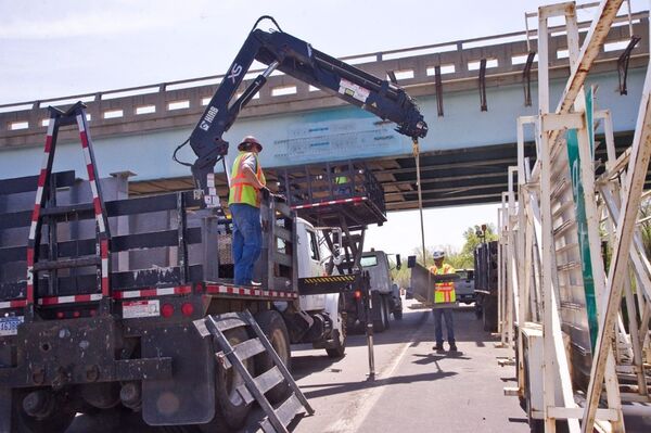
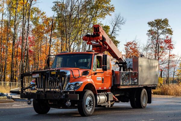
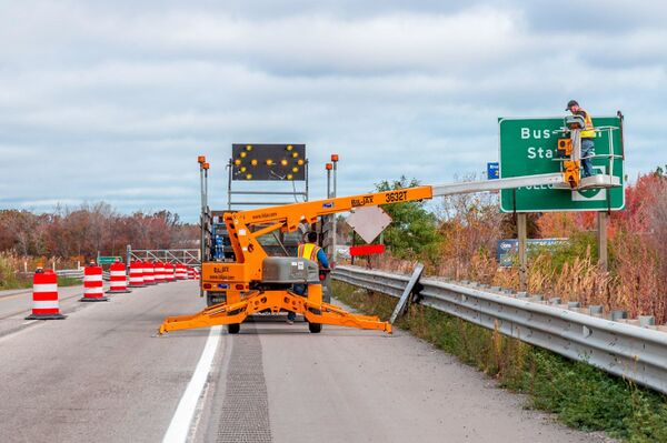
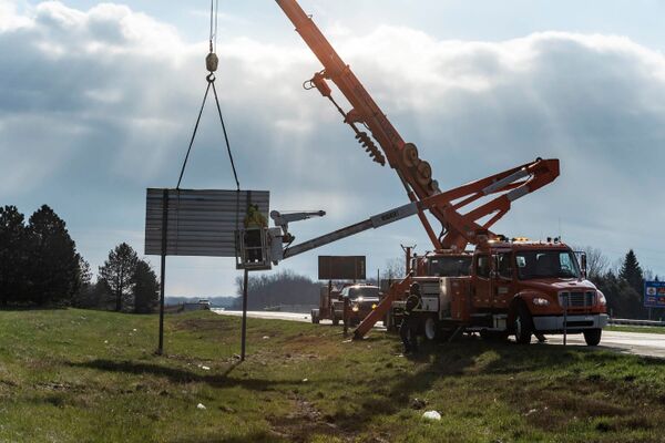
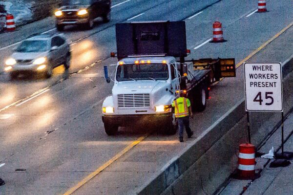
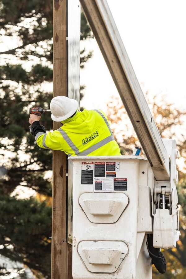
A large selection of tools, supplies and heavy machinery are necessary for the installation of ground mounted and overhead signs and their supports. Below are a just a few examples of items that may be applicable for construction of permanent signing projects.
Trucks/Machinery
- Truck mounted Cranes, Augers & Hydraulic Post drivers
- Truck mounted booms
- Light towers (for nighttime installation activities)
- Backhoe
Survey
- Lasers & Levels (4 foot levels for checking plumb of Posts and/or Uprights)
- Stakes, Flagging tape, marking utensils
- Upside-down paint (for staking/marking posts)
- Survey Rods
- Transit levels
Tools
- Concrete finishing tools: Used to mold and shape post foundations after pour
- Sawzalls: Used( for cutting off old Wood posts near it’s foundation
- Sledgehammers
- Torch cutters: Used for cutting off anchor rod/bolts of End supports from concrete bases
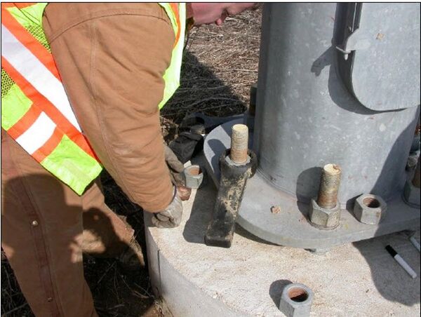
- Torque wrench, Hydraulic wrench, hand wrench
- Torque Drills, Drill bits & Hex Sockets
- Air Compressors, Air Hammers
- Angle Grinders
- Post Hole Concrete core drills & cutters
Measuring Devices
- Measuring Tapes
- Measuring Wheels
- Carpenters folding ruler: Used for measuring sign dimensions, base plate standoff.
- Laser Distance Measuring tool: Used for measuring Clearances and Span Lengths
Miscellaneous
- Nylon straps, slings and hooks
- Sand bags
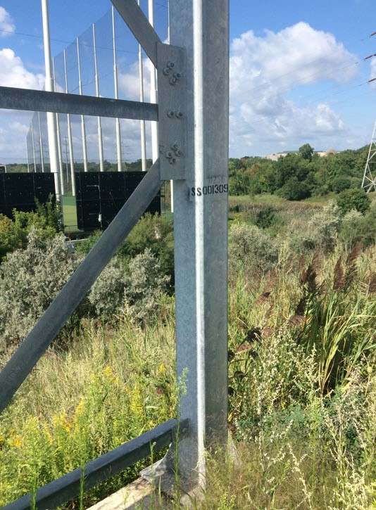
- Stencils for Sign Support Structure ID’s on uprights
- Spray paint: Used for painting structure numbers to vertical supports/poles of structures.
- Calipers: Used for measuring diameter or thickness of smaller structure components such as anchor bolts, base plate connections or component section losses.
Work safety during use of equipment and tools is of the utmost importance in signing projects. The Contractor must agree to provide the labor and supervision machinery, tools, apparatus and other means of construction; do all the work in manner of safety for their crews and the motorist; furnish all necessary resources and take any steps as may be needed to complete project in strict accordance with contract plans and the proposal to the satisfaction of the Department.
PRECONSTRUCTION
SUBMITTALS
Contract Award Information
- Contractor may view the status of award at the “Construction Contract Inquiry” site. Questions not answered there should be directed to MDOT-awards@michigan.gov
Contractor DBE Commitment
- Submit MDOT Form 2653 and any questions to MDOT-DBESheets@michigan.gov
Insurance Requirements
- Contractors will submit their insurance documents directly to ProjectWise by dropping the insurance document in the INSURANCE folder found under the Awards folder.
SHOPDRAWINGS
Working drawings of sign support structures shall be reviewed by the Project Engineer for conformance with the Standard Plans and contract requirements. The Project Engineer approves shop drawings in conformance with the standard plans. Any request to deviate from standard plans should be reviewed by the MDOT Bridge and Structures office in compliance with Structural Fabrication Quality Manual.
The working drawings of special design sign structures and/or special sign fittings shall be submitted to the MDOT Bridge and Structures office, which will coordinate approval with the Structural Fabrication Unit. After approval, the MDOT Bridge and Structures office will retain one set and forward the approved PDF file to the Project Office. The Project Engineer will forward the approved PDF file to the Contractor, who will forward to the Fabricator.
Fabrication should proceed only with approved shop drawings. However, if the Fabricator must proceed prior to receipt of approved shop drawings (performing work at their own risk), ensure that the Structural Fabrication Unit is aware of this activity and await instructions on how to proceed. If the Project Engineer permits the work to proceed without approved shop drawings, proceed with basic Quality Assurance functions using the non-approved shop drawings in accordance with the Structural Fabrication Quality Manual. Later, verify notes against the approved drawings. Notify the Structural Fabrication Unit immediately if fabrication is not in conformance with the approved shop drawings.
If a structural review is not required by the MDOT Bridge and Structures office, the Project Engineer shall initiate MDOT’s two-part acceptance process for structural products to be accepted in accordance with Section 1.1.7 of the Structural Fabrication Quality Manual.
All drawings shall be clearly marked before returned to the Contractor, whether reviewed and checked by the Project Engineer or the MDOT Bridge and Structures Office. The Project Engineer is responsible for checking the geometric features of these items. Specific items that should be checked include the following:
- Foundation Location
- Bridge Beam fascia’s
- Concrete Barrier locations
The special provisions of the contract deal to a great extent with the proper fabrication
of the signs to be installed and the manufacturing process requiring the use of approved
materials and application equipment. It is necessary, therefore, that the sign manufacturer who actually makes the signs be approved as a source of supply with certifications that meets all MDOT listed specifications requirements in accordance with Materials Source Guide.
CONSTRUCTION
Location of Signs
Since it is impossible to visualize the actual physical features of final grade elevations, vertical curves, trees, and other factors that affect proper sign placement in the initial development of signing plans, it becomes necessary to make adjustments in sign location just prior to installation. The Project Designer and Traffic Engineer should coordinate a study of each location to determine that each sign will be in the most efficient location for visibility and nighttime reflectivity. Groundmount signs may be moved up to 50 ft in either direction if severe ground, slope conditions or utilities are encountered, and constructability becomes issue. If an Advance guide sign must be moved more than 800 ft, consideration should be given to checking the distance mileage on the sign and keeping to the nearest 1 mile. In some cases, a ½ Mile sign may be necessary where location for a 1 mile is not feasible. New sign locations must be determined by Project Engineer shall be staked by the Engineer prior to installation by the Contractor.
For staking of the signs, the contractor may opt to use paint lines on existing sign supports for the inspection and final measurement of the work as called for on plans.
Sign Support Structure Identification Information
Anytime an existing cantilever, or a Truss sign structure is replaced or removed from service, the Contractor shall remove the existing sign structure in accordance with Subsection 810.03.U of the Standard Specifications for Construction. The Project Engineer will complete form 0467 of this work and submit it to MDOT Operation Field Service office so the sign support structure can be updated in the inventory system.
Sign Posts, Bridge Sign Connections and Sign Support Structures
It is important to ensure the proper torque is applied to anchor bolts connecting the bases when installing Standard Plan SIGN-300 series from MDOT’s Sign Support Standards. Procedures for assembling and inspecting high strength bolts are covered in FUSP 20SP-810H and Section 810.03 of the Standard Specifications for Construction. All base assemblies shall be checked with a torque wrench to ensure proper snug tightness of the top nut. This can be accomplished either by observing the Contractor’s torquing or by the Inspector initiating an Anchor Bolt testing with a torque wrench. Documentation of the torquing method used should be accomplished by proper entries in the Inspector’s Daily Reports.
INSPECTION & TESTING
Inspections
There are several types of inspections depending on the circumstance of the signing contract. These inspections follow those typically performed for Road, Bridge and Ancillary Structures inspections. The Michigan Ancillary Structures Inspection Manual (MiASIM) outlines procedures for performing in-service inspections of ancillary structures including, but not limited to sign support structures, DMS support structures, ESS towers, lighting towers, steel strain poles, sign trusses, wood poles, frangible lights, non-frangible lights, and mast arms.
Initial Inspection
This inspection should be performed shortly after an asset is constructed or installed. It is important to ensure anchor bolts are tightened properly and that an asset does not have any deficiencies or damage. Anchor bolts should be pretensioned in accordance with the turn-of-nut method in FUSP 20SP-810H. Anchor bolts can become loose and must be inspected in accordance with FUSP 20SP-810A. All materials furnished from the contractor additionally must be in accordance with the Standard Specification for Construction. See FUSP 20SP-810A for procedures related to requesting this inspection and contact the Ancillary Structures Unit at MDOT-Ancillary@michigan.gov with any questions. This includes those assets listed below:
- Cantilever, Type E
- Cantilever, Type J
- DMS Support Structures
- ESS Towers
- Frangible Light Pole Structures
- Non-Frangible Light Pole Structures
- Tower Lighting Structures
- Mast Arm Support Structures
- Truss, Type C & D
- Truss, Type E
- Steel Strain Poles
Routine Inspection
This can simply consist of a ground level inspection with no lane closures. Ground-mounted signs and their post supports are inspected for missing lock washers, bolts and any fastening hardware as required per Standard sign support drawings. Sign sheeting should be inspected for tears, excessive wrinkles or twisting of sheeting behind bolt heads. The spacing distance between 2 posts for one sign and it’s bottom height should be in accordance to the Standard Sign Support drawings. A installation date sticker should be checked for as applied by contractor on the back of a permanent sign.
For Inventory of Sign Support Structures, routine inspection program is recommended to obtain the structure information and quickly look for any deficiencies in and around base plates and foundations. Verify Sign Support structure Upright is Stenciled with it’s ID in accordance with the plans and Standard Specifications for Construction. A Punch list is a document created by the Department personnel or it’s representing inspectors generated from this inspection type near the projects close-out. It’s imperative to perform this inspection in a timely manner to allow time for contractor and his crews to follow upon.
Final Inspection
This would be an activity by the inspector if a sign, sign support structure or post is found to have deficiencies or other materials issues as noted from a Punch list that require more frequent inspection than the typical inspection frequency to ensure compliance with Standards and Departments satisfaction. This inspection generally follows up on with repairs, fixes and/or corrections as noted from the Punch list.
Inspection Tools
The list below is what would be considered common tools for the construction engineer and/or inspector during construction of a signing project.
- 4-foot Level: Used for checking plumbness of non-tapered vertical supports/poles and checking levelness of other components.
- Plumb Bob: Used for checking tapered and non-tapered vertical support/pole plumbness and bowing.
- Nylon string: Used for determining and measuring sag or any other distortion to a chord or other member.
- Laser Distance Measuring Tool: Used to measure clearances and span lengths.
- 25-foot Steel Tape Measure: Used for measuring sign dimensions, anchor bolt diameters, base plate standoff distances, and deficiency sizes, etc.
- Folding Ruler: Used for measuring some sign dimensions, anchor bolt diameters, base plate standoff distances, deficiency sizes, and used as a scale in photographs.
- Calipers: Used for measuring diameter or thickness of smaller structure components, such as anchor bolts, and component section losses.
- Crack Gauge: Used for measuring width of cracks.
- Feeler or Taper Gauge: Used for measuring gaps between parts or pieces such as gaps between top nuts and base plates.
- D-meter: Used for measuring thickness of components where access to one side is restricted (e.g., pole wall thickness).
- 8-foot Aluminum Range Pole: Used in prodding for scour around culvert and for placing in photos to help show depth of scour or embankment erosion
Construction personnel or it’s representative should be fully equipped to perform basic inspection activities of permanent signing projects. Additional equipment or tools may be needed as circumstances warrant to ensure a complete and thorough inspection for Quality Assurance.
These types of Inspections are for In-service construction contracts for permanent signing projects.
Other area programs conduct inspections for Sign Support Structure preservation, monitoring and inventory purposes. Refer to the Michigan Ancillary Structures Inspection Manual (MiASIM) that provides general operational guidelines as well as Inspector qualifications.
Installation Date Sticker
An installation date sticker must be hole-punched by the sign contractor and shall be attached on the back of all permanent signs that are received on the project. Signs without such indicated acceptance shall not be permitted on the project. Damaged signs shall be rejected.
At the completion of a signing project, the Project Engineer shall request appropriate personnel to assist in making a final inspection for a punch list to be addressed by Contractor.
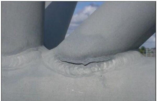
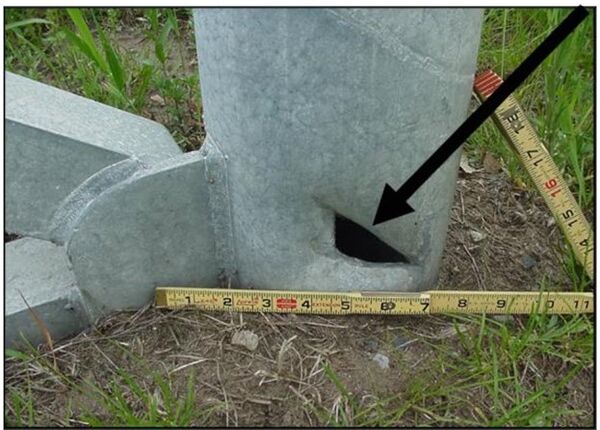
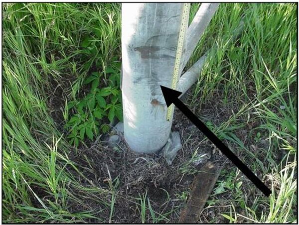
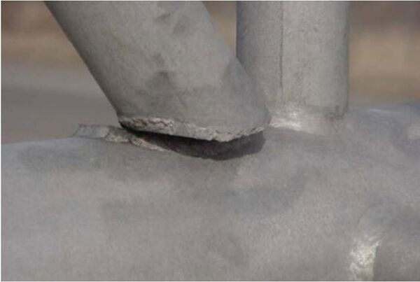
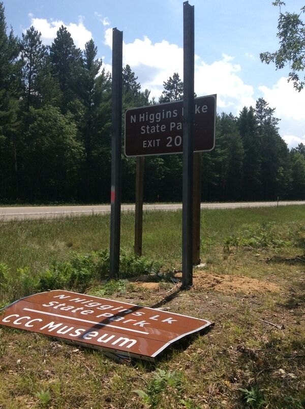
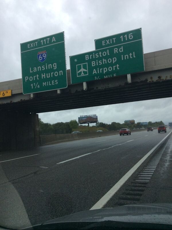
Inspection Issue Example Photographs
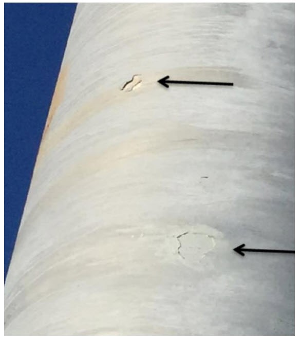
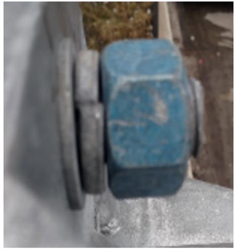
MEASUREMENT, DOCMENTATION & PAYMENT
-Reserved-
LOCAL AGENCY PROJECT CONSIDERATIONS
-Reserved-
RAIL PROJECT CONSIDERATIONS
-Reserved-
