Difference between revisions of "823 - Water Mains"
m |
|||
| (19 intermediate revisions by 3 users not shown) | |||
| Line 4: | Line 4: | ||
<center><span STYLE="font: 40pt arial;">'''Water Mains'''</span></center> | <center><span STYLE="font: 40pt arial;">'''Water Mains'''</span></center> | ||
| − | |||
| − | ==GENERAL== | + | ==[[#GENERAL|GENERAL]]== |
| + | |||
| + | Water mains are a conduit or pipe that is constructed to convey treated water for consumption or to provide water for emergency services such as Fire Departments. The pipes, which are typically cast iron, are run under pressure to provide a continuous supply of water when performing such tasks as washing dishes. | ||
| + | |||
| + | Water mains are typically maintained by local municipalities and in some instances, regional entities. | ||
| − | |||
{{top}} | {{top}} | ||
| − | ==MATERIALS== | + | ==[[#MATERIALS|MATERIALS]]== |
| + | |||
| + | === '''Pipe''' === | ||
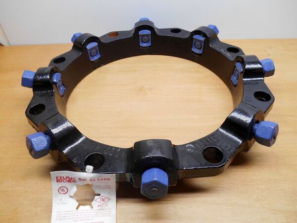
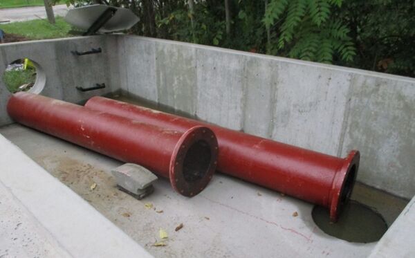
| + | Pipe material is per Section 923 of the Standard Specifications for Construction. Pipe material is typically bituminous and cement lined cast iron material with male and female ends. The bituminous lining, which is applied to the outside of the pipe helps to mitigated corrosion of the cast iron pipe as well as the cement lining which is applied to the inside of the pipe. Each section of pipe can either come with push-on joints or be bolted mechanically. Note that there may be additional material requirements as specified by the maintaining agency for the water main. | ||
| + | |||
| + | The Inspector should verify the material is acceptable for incorporation into the project by comparison to approved Material Source Lists and delivery tickets. | ||
| + | |||
| + | |||
| + | |||
| + | [[File:823-1.jpg|600px|thumb|center|'''Figure 1 - Example of Mechanical Joint Restraint''']] | ||
| + | |||
| + | |||
| + | |||
| + | [[File:823-2.jpg|600px|thumb|center|'''Figure 2 - Pipe with Flange Pipe Fitting''']] | ||
| + | |||
| + | |||
| + | === '''Water Services''' === | ||
| + | Water service material is per Section 923 of the Standard Specifications for Construction. Water services are a smaller diameter water line, usually made of copper, that feeds off the main water main line to a house or businesses. | ||
| + | |||
| + | === '''Gate Wells''' === | ||
| + | Gate wells material is per Section 909 of the Standard Specifications for Construction. Gate wells are typically precast concrete structures that provide access to gate valves. Refer to special details associated with the water main work as maintaining agencies have different requirements for gate wells. | ||
| + | |||
| + | === '''Gate Valves''' === | ||
| + | Gate valves material is per Section 923 of the Standard Specifications for Construction. Gate Valves are installed along water main runs and are intended to provide isolation points to full open or fully close a run of water main. Gates valves are operated by turning the stem to open or close the valve as you would with a household spigot. Refer to special details associated with the water main work as maintaining agencies have different requirements for gate valves. | ||
| + | |||
| + | === '''Tapping Valves''' === | ||
| + | Tapping valves material is per Section 923 of the Standard Specifications for Construction. Tapping Valves are installed along a water main that is in in place and can be installed if the pipeline service cannot be suspended. Refer to special details associated with the water main work as maintaining agencies have different requirements for tapping valves. | ||
| + | |||
| + | === '''Valve Boxes and Curb Boxes''' === | ||
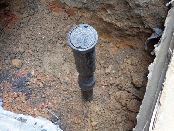
| + | Valve and Curb Boxes must meet the material requirements per Section 923 of the Standard Specifications for Construction. The boxes, made of cast iron, are installed over gate valves that are used for service shut offs or hydrants. Refer to special details associated with the water main work as maintaining agencies have different requirement. | ||
| + | |||
| + | |||
| + | |||
| + | [[File:823-3.jpg|600px|thumb|center|'''Figure 3 - Valve Box''']] | ||
| + | |||
| + | === '''Corporation Stop and Curb Stop''' === | ||
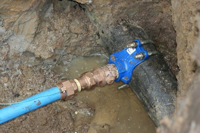
| + | Corporation stop and curb stop must meet the material requirements per Section 923 of the Standard Specifications for Construction. Corporation stop’s screw into the municple water main and a curb stop is what is used to shot of water to residence. Refer to special details associated with the water main work as maintaining agencies have different requirements. | ||
| + | |||
| + | |||
| + | |||
| + | [[File:823-4.jpg|600px|thumb|center|'''Figure 4 - Corporation Stop with Double Strap Saddle''']] | ||
| + | |||
| + | |||
| + | === '''Service Saddle''' === | ||
| + | Service Saddles must meet the material requirements per Section 923 of the Standard Specifications for Construction. Service Saddles are intended to secure a service lead to the water main, see Figure 2 for a picture of a service saddle. Refer to special details associated with the water main work as maintaining agencies have different requirements. | ||
| + | |||
| + | === '''Hydrants''' === | ||
| + | Hydrants must meet the material requirements per Section 923 of the Standard Specifications for Construction. Hydrants serve as discharge points so that water can be delivered from the distribution system. Hydrants serve as an important means of assisting emergency services. Refer to special details associated with the water main work as maintaining agencies have different requirements. | ||
| + | |||
| + | |||
| + | |||
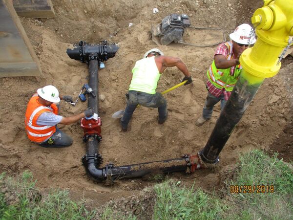
| + | [[File:823-5.jpg|600px|thumb|center|'''Figure 5 - Hydrant Installation, with Gate Valve''']] | ||
| + | |||
| + | |||
| + | === '''Backfill material''' === | ||
| + | Granular material will be used as per Section 902 of the Standard Specifications for Construction and as noted in applicable standards associated with the water main work. | ||
| + | |||
| + | The Inspector should verify the granular material is acceptable for incorporation into the project by comparison to approved Material Source Lists and delivery tickets. | ||
| + | |||
| + | === '''Polyethylene Encasement''' === | ||
| + | Polyethylene Encasement, also commonly called Polywrap, will be used as per Section 923 of the Standard Specifications for Construction and as noted in applicable standards associated with the water main work. Polywrap is common method used to protect ductile iron pipe from corrosion in certain types of soil The material works by depleting oxygen in the water trapped under the wrap and thereby reducing corrosion. | ||
| + | |||
| + | |||
| + | |||
| − | |||
{{top}} | {{top}} | ||
| − | ==CONSTRUCTION== | + | ==[[#EQUIPMENT|EQUIPMENT]]== |
| + | |||
| + | The following list of equipment can be used for water main work: | ||
| + | :* Excavators | ||
| + | :* Backhoes | ||
| + | :* Front end loaders | ||
| + | :* Occasionally bulldozers and riding vibratory rollers for aggregate compaction | ||
| + | :* Plate compactors | ||
| + | :* Ho-Pac attachments | ||
| + | :* Gas powered rammer tamping machines | ||
| + | :* Air powered pogo thumper hammers | ||
| + | :* Sand/stone boxes | ||
| + | :* Portable cement mixers | ||
| + | :* Cement/mortar mixing tubs | ||
| + | :* Portable generators | ||
| + | :* Electric submersible pumps | ||
| + | :* Trash pumps | ||
| + | :* Pipe lasers | ||
| + | :* Transit or laser levels | ||
| + | :* Leveling/grade poles | ||
| + | :* Electric impact wrenches | ||
| + | :* Pipe/spud bars | ||
| + | :* Small hand tools (shovels, levels, pipe “chop” saws, etc.) | ||
| + | :* Direct tap machine for water main taps | ||
| + | |||
| + | |||
| + | |||
| + | |||
| + | ==[[#PRECONSTRUCTION|PRECONSTRUCTION]]== | ||
| + | |||
| + | :#Prior to the start of construction, the Inspector should review the plans to verify the location of the water main work. | ||
| + | :#Verify the Contractor has requested the maintaining agency to stake existing water infrastructure. | ||
| + | :#Verify the licensed surveyor has provided stakes for the work. Typically survey stakes are offset 5 and 10 feet from the centerline of the work. There is potential that paint marks will be placed on pavement due to limited room or inability to place offset stakes. If the water main work requires the removal of existing pavement, verify the limits of the pavement removal have been marked. | ||
| + | :#The Inspector should review the plans and the Special Provision for Maintenance of Traffic. There may be restrictions or staging requirements for the installation of the water main. This is typically associated with staging requirements on a project and access to side streets and driveways. | ||
| + | :#Verify all materials are approved for use and verify that stockpiled materials are protected. Obtain photographs of material labels, storage method, and their location. | ||
| + | :#An onsite meeting with the maintaining agency should be conducted. The following topics should be discussed at the meeting: staging requirements, services, locations of valves, and exercising of valves outside the work area. Exercising existing valves within the work area and also outside of the work area should be done several weeks in advance of the work. If valves cannot be closed when exercised a discussion with the maintaining agency and Engineer will need to be conducted to determine if there are any impacts to the proposed work. | ||
| + | :#Discuss with the Contractor the methods that will be used to construct the water main. | ||
| + | :#Residents and businesses should be contacted if there will be disruptions to services. Coordination by the Contractor with impacted users may be required if disruption is necessary. | ||
| + | |||
| + | |||
| + | |||
| + | |||
| + | |||
| + | ==[[#CONSTRUCTION|CONSTRUCTION]]== | ||
| + | |||
| + | The Contractor will begin with the removal of existing pavement or aggregate material to the required depth and grade of the proposed water main work. | ||
| + | |||
| + | Once the excavation is completed per the project plans, the Contractor will lay a bedding material to rest the water main on. Individual pipes will be laid in the trench and assembled using a come along or pry bar. The installation of all pipe, fittings, and appurtenances should be in accordance with the manufacturer’s recommendations. It is important at this time that the Contractor make every effort to avoid debris from entering the water main as it is being placed. | ||
| + | |||
| + | The Contractor will place backfill material and compact the material with a hand operated compactor to receive required density. After that, the Contactor will place the remaining backfill per the plans, and will compact the fill by mechanical means. | ||
| + | |||
| + | After the completion of the installation of the water main, the Contractor will then perform a pressure test and bacteriological test on the water main. This test, which is done in conjunction with the maintaining agency, will confirm that the water main is ready to be connected to the distribution system. This process of testing can take up to two weeks. | ||
| − | |||
{{top}} | {{top}} | ||
| − | ==MEASUREMENT AND PAYMENT== | + | ==[[#INSPECTION & TESTING|INSPECTION & TESTING]]== |
| + | |||
| + | The Inspector should utilize, at a minimum, the following tools to perform required inspection: | ||
| + | :* 100-foot tape or longer | ||
| + | :* 25-foot tape | ||
| + | :* Measuring wheel | ||
| + | :* Chaining pin | ||
| + | :* 6-foot stick ruler | ||
| + | :* 4-foot level | ||
| + | :* Working plans | ||
| + | :* As-built sheets to update the plans | ||
| + | :* Survey rod | ||
| + | :* Camera for obtaining photos | ||
| + | |||
| + | The following steps should be taken by the Inspector prior to the start of construction: | ||
| + | :#Obtain approved drawings and specifications for review. Study the components and layout and review of the Contractor’s installation procedures. | ||
| + | :#Verify all materials being incorporated into the project. | ||
| + | :#Coordinate with the Surveyor to stake the limits of the work. | ||
| + | :#Coordinate with the maintaining agency to exercise all valves within and just outside the construction work . | ||
| + | :#Verify with the maintaining agency all locations of service leads on the project. This will include the material type. If the service is of a material other then copper the service will need to be replaced to the building. If the plans do not show a service or if the existing material is not copper bring this to the attention of the Engineer. It is important to note that service leads, that are not copper, need to be replaced from the main to the building in one run. Staged replacement is not allowed. | ||
| + | |||
| + | The following steps should be taken by the Inspector during construction: | ||
| + | :#Observe installation pipe, fittings, and appurtenances in accordance with manufacturer’s recommendations. | ||
| + | :#Monitor the excavation of the trench to verify the top of pipe meets the minimum depth requirements shown on the plans. The minimum trench width should be 3 to 4 times the pipe diameter to allow for work on all sides of the pipe, unless specified on the plans. | ||
| + | :#Verify that all pipe bedding and backfill of excavated trenches is clean, dry, and meets design requirements. | ||
| + | :#When the contractor is connecting two pipes, ensure the pipe bell is clean and install the required joint gasket. Verify there is no debris in the pipe before installation. Verify the contractor lubricates the gasket and spigot immediately prior to assembly. The contractor should not use an excavator to “drive the pipe home” as this can damage the pipe. | ||
| + | :##Verify the correct gasket is used as one manufacturer’s specific gasket may not fit a different manufacturer’s pipe. | ||
| + | :##Obtain grade shots every 50 feet and document the grades on the as-built plans. | ||
| + | :##Obtain offset location of the water main. Use an existing feature that will not be subject to removal, this includes a curb line or building. | ||
| + | :##Obtain offset location for any deflections. | ||
| + | :##Record this information on the as-built document. | ||
| + | :##Use a temporary plug at the pipe’s open end to prevent entrance of foreign materials. | ||
| + | |||
| + | |||
| + | |||
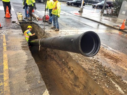
| + | [[File:823-6.jpg|600px|thumb|center|'''Figure 6 - Laying Pipe in Trench''']] | ||
| + | |||
| + | |||
| + | :#Verify the contractor sets valves, fittings, and hydrants to plan locations. Document the locations with stationing and offsets. | ||
| + | :##Verify mechanical joints are tightened evenly and gasketed joints are restrained with “gripper gaskets” per the manufacturer. | ||
| + | :##Obtain grade shots for each location. | ||
| + | :##Obtain offset location from an existing feature that will not be subject to removal. Record this information on the as-built document. | ||
| + | :##The contractor should provide thrust control at all fittings. Requirements can verify by maintaining agency. Verify that an approved thrust block is used. A detail may be included in the project plans. | ||
| + | :##Obtain offset and depth location for each thrust control and verify distance from each fitting. | ||
| + | |||
| + | |||
| + | |||
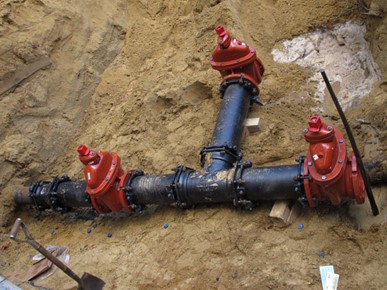
| + | [[File:823-7.jpg|600px|thumb|center|'''Figure 7 - Water Main with Gate Valves, Tee and Reducer''']] | ||
| + | |||
| + | |||
| + | :#Service leads: | ||
| + | :##Service leads typically are tapped at 45 degrees above the center of the water main pipe. Run service leads at a 90-degree angle from the distribution line. | ||
| + | :###Document the location of the tap, both depth and distance from a point that will not be subject to removal. | ||
| + | :####Record this information on the as-built document. | ||
| + | :###Some maintaining agencies require a service card in which a diagram of the install is presented. | ||
| + | :##Service leads are required to be copper. If a service lead is found during construction, that wasn’t called out on the plans, bring this to the attention of the Engineer immediately. | ||
| + | :##If replacing an existing service that is not made of copper the service will have to be replaced from the main to the building in one stage/run, regardless of any associated roadway construction staging. Water services may not be replaced part-width unless the existing service is copper. This is a requirement of the Michigan Department of Environment, Great Lakes, and Energy (EGLE) | ||
| + | :#Polyethylene encasement: | ||
| + | :##Before a pipe is placed in the utility trench, the Contractor will slip the polyethylene wrap (commonly referred to as “poly wrap” around the pipe. Loose ends will be taped. | ||
| + | :#Backfill: | ||
| + | :##Tamp additional bedding in place up the midpoint of the utility and consolidate this material under the pipe’s spring point. Use hand operated compactors to achieve the required compaction. | ||
| + | :##Place bedding in maximum lifts of 8 to 12 inches using approved trench backfill material as indicated in the project plans. | ||
| + | :##Obtain density shots for each lift. | ||
| + | :#Pressure and bacteriological testing: | ||
| + | :##Pressure test: | ||
| + | :###A pressure test consists of a specified pressure performed over a 2-hour period. The maintaining agency will typically observe the testing. | ||
| + | :###Acceptance of the pressure test will be based on the project specifications. The testing procedures verify compliance for the size and length of the pipe. | ||
| + | :###If the pressure test fails, the Contractor will be required to find the leak and repair it. A new pressure test will be performed. | ||
| + | :###Document results and approval from maintaining agency. | ||
| + | :##Bacteriological Test (Bac-T): | ||
| + | :###Consists of flushing, disinfection, and 2 consecutive safe samples taken at 24-hour intervals for each section of pipe tested. | ||
| + | :###Coordination with the maintaining agency is required following the successful pressure test. | ||
| + | :###A failure of one test will require retesting. | ||
| + | :###Document results and approval from maintaining agency. | ||
| + | :#Final tie-in of new main into an existing main: | ||
| + | :##Upon completion of the required testing, the Contractor’s tie-in work will take place. The Contractor will disinfect the remaining piece of pipe needed to connect the new water main to the existing main with a chlorine swab. This work needs to be verified by the Inspector. Because the connection piece is not Bac-T tested, there is a maximin length allowed for connection. See contract documents or contact engineer for specific maintaining agency requirements. | ||
| + | |||
| + | |||
| + | |||
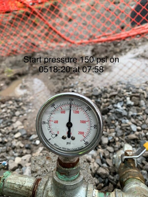
| + | [[File:823-8.jpg|600px|thumb|center|'''Figure 8 - Pressure Test''']] | ||
| + | |||
| + | ==[[#MEASUREMENT AND PAYMENT|MEASUREMENT AND PAYMENT]]== | ||
| + | |||
| + | The primary report required for the payment of water main is the Inspector’s Daily Report. The Inspector should note in the remarks section of the report the condition of the base material during excavation, what type of forms were used, material verification, and equipment used for the placement of the water main | ||
| + | |||
| + | Sketches and as-built documentation are critical information that will need be obtained. Once the main is covered, locations of fittings, deflections, or service leads will be difficult to obtain. For all associated water main work the as-built documentation should contain: | ||
| + | :#Length of water main installed, measured from the center of gate well or mechanical joint. The offset of the water main from an object not subject to removal or displacement over time. | ||
| + | :#Grade shots of the water main work. | ||
| + | :#Volume of backfill material placed. | ||
| + | |||
| + | Sketches should be utilized for the calculation of the quantity that was placed. This will include measurements as described to accurately reflect what was installed. | ||
| + | |||
| + | The Inspector will need to utilized Form 1174R, Inspectors’ Report of Concrete Placed, for each day the Contractor pours concrete. This work is associated with thrust blocks. The form should be distributed as called out and the Inspector should include this with the IDR. | ||
| + | |||
| + | With each IDR the Inspector should include a copy of Form 0582B, Moisture & Density Determination – Nuclear Method. | ||
| + | |||
| + | Delivery tickets must be verified for the source of material against approved Material Source List. Each ticket should contain the following: | ||
| + | :#Material producer with MDOT certified pit number. | ||
| + | :#Ticket serial number. | ||
| + | :#Contractor name and MDOT project number. | ||
| + | :#Date and time of ticket. | ||
| + | :#Signed certification from the producer of the material. | ||
| + | :#Automated printout of weights and materials. | ||
| + | |||
| − | |||
{{top}} | {{top}} | ||
| + | |||
| + | [[Category:Construction Manual]] | ||
| + | [[Category: Division 8]] | ||
| + | [[Category: Section 823]] | ||
| + | [[Category: New CM Format]] | ||
Latest revision as of 14:01, 27 September 2023
GENERAL
Water mains are a conduit or pipe that is constructed to convey treated water for consumption or to provide water for emergency services such as Fire Departments. The pipes, which are typically cast iron, are run under pressure to provide a continuous supply of water when performing such tasks as washing dishes.
Water mains are typically maintained by local municipalities and in some instances, regional entities.
MATERIALS
Pipe
Pipe material is per Section 923 of the Standard Specifications for Construction. Pipe material is typically bituminous and cement lined cast iron material with male and female ends. The bituminous lining, which is applied to the outside of the pipe helps to mitigated corrosion of the cast iron pipe as well as the cement lining which is applied to the inside of the pipe. Each section of pipe can either come with push-on joints or be bolted mechanically. Note that there may be additional material requirements as specified by the maintaining agency for the water main.
The Inspector should verify the material is acceptable for incorporation into the project by comparison to approved Material Source Lists and delivery tickets.
Water Services
Water service material is per Section 923 of the Standard Specifications for Construction. Water services are a smaller diameter water line, usually made of copper, that feeds off the main water main line to a house or businesses.
Gate Wells
Gate wells material is per Section 909 of the Standard Specifications for Construction. Gate wells are typically precast concrete structures that provide access to gate valves. Refer to special details associated with the water main work as maintaining agencies have different requirements for gate wells.
Gate Valves
Gate valves material is per Section 923 of the Standard Specifications for Construction. Gate Valves are installed along water main runs and are intended to provide isolation points to full open or fully close a run of water main. Gates valves are operated by turning the stem to open or close the valve as you would with a household spigot. Refer to special details associated with the water main work as maintaining agencies have different requirements for gate valves.
Tapping Valves
Tapping valves material is per Section 923 of the Standard Specifications for Construction. Tapping Valves are installed along a water main that is in in place and can be installed if the pipeline service cannot be suspended. Refer to special details associated with the water main work as maintaining agencies have different requirements for tapping valves.
Valve Boxes and Curb Boxes
Valve and Curb Boxes must meet the material requirements per Section 923 of the Standard Specifications for Construction. The boxes, made of cast iron, are installed over gate valves that are used for service shut offs or hydrants. Refer to special details associated with the water main work as maintaining agencies have different requirement.
Corporation Stop and Curb Stop
Corporation stop and curb stop must meet the material requirements per Section 923 of the Standard Specifications for Construction. Corporation stop’s screw into the municple water main and a curb stop is what is used to shot of water to residence. Refer to special details associated with the water main work as maintaining agencies have different requirements.
Service Saddle
Service Saddles must meet the material requirements per Section 923 of the Standard Specifications for Construction. Service Saddles are intended to secure a service lead to the water main, see Figure 2 for a picture of a service saddle. Refer to special details associated with the water main work as maintaining agencies have different requirements.
Hydrants
Hydrants must meet the material requirements per Section 923 of the Standard Specifications for Construction. Hydrants serve as discharge points so that water can be delivered from the distribution system. Hydrants serve as an important means of assisting emergency services. Refer to special details associated with the water main work as maintaining agencies have different requirements.
Backfill material
Granular material will be used as per Section 902 of the Standard Specifications for Construction and as noted in applicable standards associated with the water main work.
The Inspector should verify the granular material is acceptable for incorporation into the project by comparison to approved Material Source Lists and delivery tickets.
Polyethylene Encasement
Polyethylene Encasement, also commonly called Polywrap, will be used as per Section 923 of the Standard Specifications for Construction and as noted in applicable standards associated with the water main work. Polywrap is common method used to protect ductile iron pipe from corrosion in certain types of soil The material works by depleting oxygen in the water trapped under the wrap and thereby reducing corrosion.
EQUIPMENT
The following list of equipment can be used for water main work:
- Excavators
- Backhoes
- Front end loaders
- Occasionally bulldozers and riding vibratory rollers for aggregate compaction
- Plate compactors
- Ho-Pac attachments
- Gas powered rammer tamping machines
- Air powered pogo thumper hammers
- Sand/stone boxes
- Portable cement mixers
- Cement/mortar mixing tubs
- Portable generators
- Electric submersible pumps
- Trash pumps
- Pipe lasers
- Transit or laser levels
- Leveling/grade poles
- Electric impact wrenches
- Pipe/spud bars
- Small hand tools (shovels, levels, pipe “chop” saws, etc.)
- Direct tap machine for water main taps
PRECONSTRUCTION
- Prior to the start of construction, the Inspector should review the plans to verify the location of the water main work.
- Verify the Contractor has requested the maintaining agency to stake existing water infrastructure.
- Verify the licensed surveyor has provided stakes for the work. Typically survey stakes are offset 5 and 10 feet from the centerline of the work. There is potential that paint marks will be placed on pavement due to limited room or inability to place offset stakes. If the water main work requires the removal of existing pavement, verify the limits of the pavement removal have been marked.
- The Inspector should review the plans and the Special Provision for Maintenance of Traffic. There may be restrictions or staging requirements for the installation of the water main. This is typically associated with staging requirements on a project and access to side streets and driveways.
- Verify all materials are approved for use and verify that stockpiled materials are protected. Obtain photographs of material labels, storage method, and their location.
- An onsite meeting with the maintaining agency should be conducted. The following topics should be discussed at the meeting: staging requirements, services, locations of valves, and exercising of valves outside the work area. Exercising existing valves within the work area and also outside of the work area should be done several weeks in advance of the work. If valves cannot be closed when exercised a discussion with the maintaining agency and Engineer will need to be conducted to determine if there are any impacts to the proposed work.
- Discuss with the Contractor the methods that will be used to construct the water main.
- Residents and businesses should be contacted if there will be disruptions to services. Coordination by the Contractor with impacted users may be required if disruption is necessary.
CONSTRUCTION
The Contractor will begin with the removal of existing pavement or aggregate material to the required depth and grade of the proposed water main work.
Once the excavation is completed per the project plans, the Contractor will lay a bedding material to rest the water main on. Individual pipes will be laid in the trench and assembled using a come along or pry bar. The installation of all pipe, fittings, and appurtenances should be in accordance with the manufacturer’s recommendations. It is important at this time that the Contractor make every effort to avoid debris from entering the water main as it is being placed.
The Contractor will place backfill material and compact the material with a hand operated compactor to receive required density. After that, the Contactor will place the remaining backfill per the plans, and will compact the fill by mechanical means.
After the completion of the installation of the water main, the Contractor will then perform a pressure test and bacteriological test on the water main. This test, which is done in conjunction with the maintaining agency, will confirm that the water main is ready to be connected to the distribution system. This process of testing can take up to two weeks.
INSPECTION & TESTING
The Inspector should utilize, at a minimum, the following tools to perform required inspection:
- 100-foot tape or longer
- 25-foot tape
- Measuring wheel
- Chaining pin
- 6-foot stick ruler
- 4-foot level
- Working plans
- As-built sheets to update the plans
- Survey rod
- Camera for obtaining photos
The following steps should be taken by the Inspector prior to the start of construction:
- Obtain approved drawings and specifications for review. Study the components and layout and review of the Contractor’s installation procedures.
- Verify all materials being incorporated into the project.
- Coordinate with the Surveyor to stake the limits of the work.
- Coordinate with the maintaining agency to exercise all valves within and just outside the construction work .
- Verify with the maintaining agency all locations of service leads on the project. This will include the material type. If the service is of a material other then copper the service will need to be replaced to the building. If the plans do not show a service or if the existing material is not copper bring this to the attention of the Engineer. It is important to note that service leads, that are not copper, need to be replaced from the main to the building in one run. Staged replacement is not allowed.
The following steps should be taken by the Inspector during construction:
- Observe installation pipe, fittings, and appurtenances in accordance with manufacturer’s recommendations.
- Monitor the excavation of the trench to verify the top of pipe meets the minimum depth requirements shown on the plans. The minimum trench width should be 3 to 4 times the pipe diameter to allow for work on all sides of the pipe, unless specified on the plans.
- Verify that all pipe bedding and backfill of excavated trenches is clean, dry, and meets design requirements.
- When the contractor is connecting two pipes, ensure the pipe bell is clean and install the required joint gasket. Verify there is no debris in the pipe before installation. Verify the contractor lubricates the gasket and spigot immediately prior to assembly. The contractor should not use an excavator to “drive the pipe home” as this can damage the pipe.
- Verify the correct gasket is used as one manufacturer’s specific gasket may not fit a different manufacturer’s pipe.
- Obtain grade shots every 50 feet and document the grades on the as-built plans.
- Obtain offset location of the water main. Use an existing feature that will not be subject to removal, this includes a curb line or building.
- Obtain offset location for any deflections.
- Record this information on the as-built document.
- Use a temporary plug at the pipe’s open end to prevent entrance of foreign materials.
- Verify the contractor sets valves, fittings, and hydrants to plan locations. Document the locations with stationing and offsets.
- Verify mechanical joints are tightened evenly and gasketed joints are restrained with “gripper gaskets” per the manufacturer.
- Obtain grade shots for each location.
- Obtain offset location from an existing feature that will not be subject to removal. Record this information on the as-built document.
- The contractor should provide thrust control at all fittings. Requirements can verify by maintaining agency. Verify that an approved thrust block is used. A detail may be included in the project plans.
- Obtain offset and depth location for each thrust control and verify distance from each fitting.
- Verify the contractor sets valves, fittings, and hydrants to plan locations. Document the locations with stationing and offsets.
- Service leads:
- Service leads typically are tapped at 45 degrees above the center of the water main pipe. Run service leads at a 90-degree angle from the distribution line.
- Document the location of the tap, both depth and distance from a point that will not be subject to removal.
- Record this information on the as-built document.
- Some maintaining agencies require a service card in which a diagram of the install is presented.
- Document the location of the tap, both depth and distance from a point that will not be subject to removal.
- Service leads are required to be copper. If a service lead is found during construction, that wasn’t called out on the plans, bring this to the attention of the Engineer immediately.
- If replacing an existing service that is not made of copper the service will have to be replaced from the main to the building in one stage/run, regardless of any associated roadway construction staging. Water services may not be replaced part-width unless the existing service is copper. This is a requirement of the Michigan Department of Environment, Great Lakes, and Energy (EGLE)
- Service leads typically are tapped at 45 degrees above the center of the water main pipe. Run service leads at a 90-degree angle from the distribution line.
- Polyethylene encasement:
- Before a pipe is placed in the utility trench, the Contractor will slip the polyethylene wrap (commonly referred to as “poly wrap” around the pipe. Loose ends will be taped.
- Backfill:
- Tamp additional bedding in place up the midpoint of the utility and consolidate this material under the pipe’s spring point. Use hand operated compactors to achieve the required compaction.
- Place bedding in maximum lifts of 8 to 12 inches using approved trench backfill material as indicated in the project plans.
- Obtain density shots for each lift.
- Pressure and bacteriological testing:
- Pressure test:
- A pressure test consists of a specified pressure performed over a 2-hour period. The maintaining agency will typically observe the testing.
- Acceptance of the pressure test will be based on the project specifications. The testing procedures verify compliance for the size and length of the pipe.
- If the pressure test fails, the Contractor will be required to find the leak and repair it. A new pressure test will be performed.
- Document results and approval from maintaining agency.
- Bacteriological Test (Bac-T):
- Consists of flushing, disinfection, and 2 consecutive safe samples taken at 24-hour intervals for each section of pipe tested.
- Coordination with the maintaining agency is required following the successful pressure test.
- A failure of one test will require retesting.
- Document results and approval from maintaining agency.
- Pressure test:
- Final tie-in of new main into an existing main:
- Upon completion of the required testing, the Contractor’s tie-in work will take place. The Contractor will disinfect the remaining piece of pipe needed to connect the new water main to the existing main with a chlorine swab. This work needs to be verified by the Inspector. Because the connection piece is not Bac-T tested, there is a maximin length allowed for connection. See contract documents or contact engineer for specific maintaining agency requirements.
- Service leads:
MEASUREMENT AND PAYMENT
The primary report required for the payment of water main is the Inspector’s Daily Report. The Inspector should note in the remarks section of the report the condition of the base material during excavation, what type of forms were used, material verification, and equipment used for the placement of the water main
Sketches and as-built documentation are critical information that will need be obtained. Once the main is covered, locations of fittings, deflections, or service leads will be difficult to obtain. For all associated water main work the as-built documentation should contain:
- Length of water main installed, measured from the center of gate well or mechanical joint. The offset of the water main from an object not subject to removal or displacement over time.
- Grade shots of the water main work.
- Volume of backfill material placed.
Sketches should be utilized for the calculation of the quantity that was placed. This will include measurements as described to accurately reflect what was installed.
The Inspector will need to utilized Form 1174R, Inspectors’ Report of Concrete Placed, for each day the Contractor pours concrete. This work is associated with thrust blocks. The form should be distributed as called out and the Inspector should include this with the IDR.
With each IDR the Inspector should include a copy of Form 0582B, Moisture & Density Determination – Nuclear Method.
Delivery tickets must be verified for the source of material against approved Material Source List. Each ticket should contain the following:
- Material producer with MDOT certified pit number.
- Ticket serial number.
- Contractor name and MDOT project number.
- Date and time of ticket.
- Signed certification from the producer of the material.
- Automated printout of weights and materials.
