Difference between revisions of "Category:Project PDF"
Wilkersonj1 (talk | contribs) m (→Changes to Deliverables: Text Cleanup) |
Wilkersonj1 (talk | contribs) m (→Sheet Scale: text edit) |
||
| Line 147: | Line 147: | ||
Different scales may be used at the design teams discretion. | Different scales may be used at the design teams discretion. | ||
| − | The Project PDF should be limited to a ''' | + | The Project PDF should be limited to a '''36 inches Height''' so that the PDF can be printed by a standard plotter. Regardless of scale, the length of a single PDF sheet '''cannot exceed 200 inches'''. This is a PDF standard and many PDF viewers will not function properly of the sheet is larger than 200 inches. This translates to approximately 3.5 miles per sheet at 100 scale. |
The length of the individual sheets can vary in the combined PDF document. | The length of the individual sheets can vary in the combined PDF document. | ||
Revision as of 10:49, 18 February 2021
Purpose
The purpose of this page is to give guidance to MDOT and Consultant designers on how to deliver a Project PDF project. For questions, concerns, or information that is lacking on this page, please contact MDOT Digital Delivery Support
Changes to Deliverables
Project PDF changes the conventional contract deliverables by replacing 11X17 plan sheets of the roadway plan and profile with PDF sheets of up to 200 inches in length. In addition, Project PDF sheets will be printed in color, and with layers (Equivalent to levels in MicroStation) enabled in the PDF document.
Project PDF does not eliminate the need for all 11X17 plan sheets. Items such as typical cross sections, survey information sheets and detail sheets will still be included on standard 11X17 plan sheets. Plan set deliverables to be included in Project PDF pilots include:
XXXXXX_Road.pdf - 11X17 plan sheets only. Contains sheets that are not included in the PlanView or ProfileView documents.
XXXXXX_Road_PlanView.pdf - Project PDF sheets of the Plan View
XXXXXX_Road_ProfileView.pdf - Project PDF sheets of the all profiles on the project (1 alignment per sheet)
There is still a 30 MB file size limit for each individual PDF set. If any of the PDF's above exceed 30 MB they should be split into multiple documents and renamed per the following example:
XXXXXX_Road1_XXX
XXXXXX_Road2_XXX
The sheet index below makes recommendations for where a typical plan sheet type would be found in a Project PDF project. These recommendations may be modified on a project basis at the design team’s discretion. The bridge plans, proposal, and supporting document deliverables are not changed by the Project PDF.
The order of the plan sheets should the same as that of the MDOT standard sheet index.
| Section 1 - Road Plans | Location in Deliverables |
|---|---|
| Title | XXXXXX_Road.pdf |
| Project Information | XXXXXX_Road.pdf |
| Legend | XXXXXX_Road.pdf |
| ROW Vicinity / Drainage Map | XXXXXX_Road_Plan.pdf |
| Note | XXXXXX_Road.pdf |
| Miscellaneous Quantities | XXXXXX_Road.pdf |
| Typical Cross Sections | XXXXXX_Road.pdf |
| Miscellaneous Details | XXXXXX_Road.pdf |
| Survey Information | XXXXXX_Road.pdf |
| Alignment | XXXXXX_Road_Plan.pdf |
| Removal, Construction, Drainage | XXXXXX_Road_Plan.pdf |
| Profile | XXXXXX_Road_Profile.pdf |
| Water Main & Sanitary Sewer | XXXXXX_Road_Plan.pdf |
| Maintaining Traffic Staging Plans / Detours | XXXXXX_Road_Plan.pdf |
| Maintaining Traffic Typical Cross Sections | XXXXXX_Road.pdf |
| Detail Grades | XXXXXX_Road_Plan.pdf |
| Culvert Plans | XXXXXX_Road.pdf |
| Detention Basin Details | XXXXXX_Road.pdf |
| Wetland Mitigation | XXXXXX_Road.pdf |
| Rest Area / Landscape | XXXXXX_Road_Plan.pdf |
| Permanent Signing | XXXXXX_Road_Plan.pdf |
| Pavement marking | XXXXXX_Road_Plan.pdf |
| Lighting | XXXXXX_Road_Plan.pdf |
| ITS | XXXXXX_Road_Plan.pdf |
| Signal | XXXXXX_Road.pdf |
| Log of Borings | XXXXXX_Road.pdf |
| Special Details | XXXXXX_Road.pdf |
Creating Project PDFs from Microstation
Previous pilots of the Project PDF included layers in the PDF which could be used to customize what was visible in the PDF. Individual sheet types (removal, construction etc) were included as 1 single PDF sheet with bookmarks that controlled the layers that were displayed on the sheets. Due to issues with rendering the bookmarks on mobile devices, this will no longer be the case on future Project PDF projects.
Project PDF Pilots will now include individual sheets for each sheet type. The Microstation levels that appear on the sheet will still be exported to the PDF using the Project PDF Plot Driver
Plan sheets that appear in the Project PDF portion of the contract documents will be printed in color. A Color Pen Table has been created for use on the pilot projects.
A workflow for creating a Project PDF from Microstation has been created to aid in the Project PDF creation Process. Project PDF sheet sizes are not currently supported by Print Organizer. MDOT Engineering Support is investigating changes to the MDOT02 workspace that would make this possible.
Sheet Scale
The recommended scales for a typical Project PDF are:
Plan view: 1" = 100'
Profile Horizontal: 1" = 100'
Profile Vertical: 1" = 10'
Different scales may be used at the design teams discretion.
The Project PDF should be limited to a 36 inches Height so that the PDF can be printed by a standard plotter. Regardless of scale, the length of a single PDF sheet cannot exceed 200 inches. This is a PDF standard and many PDF viewers will not function properly of the sheet is larger than 200 inches. This translates to approximately 3.5 miles per sheet at 100 scale.
The length of the individual sheets can vary in the combined PDF document.
Sheet Labeling
Project PDF sheets should be labeled in accordance with the MDOT Road Sample Plans.
Labels that are typically shown repetitively on every sheet should be labeled approximately every 2,500’ at 100 scale. This distanced should be scaled accordingly for scales other than 1" = 100'. Examples include alignment name labels, existing materials, utility labels, etc.
Horizontal curve data on the alignment sheets should be shown near the curve that the data applies to.
Profile grid elevations should be shown every 1,000 feet at 100 scale so that elevations are visible when zoomed in. This distance should be scaled accordingly for scales other than 1" = 100'. Profile grid stations should be duplicated on each profile port (left right and center) in an area that is visible when zoomed in. Profile strip grades should be shown below the Plan Grade profile in a location that is visible when zoomed in.
Profile sheets should generally include three profile ports (Left, Right and Center) in accordance with the MDOT Sample Plans.
Crossroad and railroad names should be shown in two locations:
- Parallel to the crossroad near the intersection using the MDOT 1.5 text style
- At the top and bottom of the sheet border using a non-standard text size that is easily readable when fully zoomed to page extents in the PDF. For a sheet that is 200 inches long, this text should be 10 times the size of MDOT 1.5. This value can be adjusted accordingly for differing sheet lengths.
The north arrow should be scaled so that it is easily viewable when zoomed to page extents in the PDF. For a sheet that is 200 inches long, this cell should be 10 times the normal size. This value can be adjusted accordingly for differing sheet lengths.
Sheet Shading
Plan sheets should use 40% transparent shading rather than patterns for all removal and construction patterns. This change was made to that the plans can be easily viewable on any device without causing long load times in the PDF.
This can be achieved by using either complex shapes or regions with fill turned on. The levels used should be the same standard levels that are provided in the MDOT workspace. For example, HMA Surface Remove would use the associated pattern level of "Surf_Pavt_HMA_Ex_Rem_As:HMASurf_Pattern".
The standard legend sheet should be modified to include a "Project Specific" area to identify which colors indicate which quantities. The standard colors in the MDOT workspace may be modified if multiple pay items use the same color. The 11X17 legend sheets should be printed in color.
Sheet Numbering
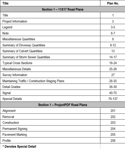
Project PDF sheets should be numbered such that the first sheet number is one sheet after an even interval of 100 (101, 201, 301 etc.) The gap in sheet numbering will allow for sheets to be added / changed during the final project review without impacting the sheet numbers of the Project PDF sheets.
The conventional 11X17 plan sheets and the Project PDF sheets should be clearly indicated on the Project Info sheet per the example below.
Sheet Quantities
Quantities will still be included in the 11X17 portion of the pilot deliverables if those quantities are applicable to the sheet. Examples of this could include signal sheets, guardrail details, or culvert details that are being provided in the 11X17 portion of the plans.
Sheet wide quantities will not be included on the Project PDF plans. Instead, they will be shown in a spreadsheet that is created by MDOT central office staff from the XML files that are delivered with the final project submittal.
Items of work that are not identifiable on the plan sheets should either be included in a table, or their pay items and quantities should be labeled in the plans. Examples of this include culverts, drainage tables, driveway tables, or guardrail items. If the items of work are included in table format then they should be shown in the 11X17 plans immediately after the Miscellaneous Details. Please note that the spreadsheet of quantities created by MDOT central office is reference information, and is not part of the contract documents.
It is recommended that quantities be broken down by roadway (northbound, southbound, rampX, etc) for quantities that would typically be paid for on the Project PDF sheets. The TSC that will be overseeing the work should be consulted to determine if this breakdown will be adequate.
XML deliverables with quantity breakdowns will still be required. This XML file will be used by MDOT central office staff to create a spreadsheet of quantities, which will be included in the Reference Information documents.
Quantity Breakdowns
It is highly encouraged that the MDOT Project Quantity Spreadsheet (PQS) be used in order to appropriately break down quantities by their respective quantity area. SAPW is limited to 8 characters in the breakdown ID field which does not lend itself well to Project PDF Projects. The information and examples below show how the PQS should be set up for Project PDF projects.
Before you Begin
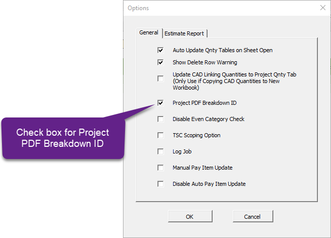
In order for quantity breakdowns to be appropriately exported to XML by the PQS, the Project PDF option must first be enabled. This changes the Sheet No column on the Plan Sheets tab so that it automates the creation of quantity breakdowns when exported to XML.
Breakdown Naming Conventions for Various Scenarios
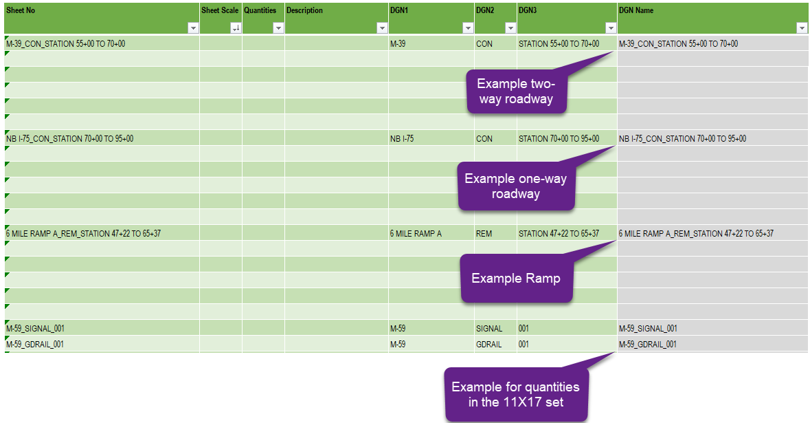
The "Sheet No" column on the plan sheets tab defines the quantity breakdowns that will be exported to XML. The image below shows examples for various scenarios that could occur on a Project PDF project.
DGN 1 should always be the roadway that the quantity applies to. DGN 2 should always be the type of sheet that the quantity appears on. DGN 3 is used to break the quantity by the appropriate area. DGN 1 and DGN 2 should generally follow the Cadd Filenames.pdf naming contentions.
Additional RID Requirements
In addition to the standard RID deliverables, all project PDF’s must include the following files as part of the RID process
Q-XXXXXX_Quantities_Removal.KMZ – A KMZ file with the layers that represent removal quantities exported to a KMZ file
Q-XXXXXX_Quantities_Construction.KMZ – A KMZ file with the layers that represent construction quantities exported to a KMZ file
A workflow for creating quantity KMZ files has been created to aid road designers on this new process.
Example Project PDFs
Example Project PDFs from previous pilots are being provided for information only. These samples do not necessarily reflect the guidance given on this page. In the case that Project PDF examples conflict with the guidance on this page, follow the guidance given on this page.
This category currently contains no pages or media.


