Difference between revisions of "Chapter 10 - Deliverables"
(→Raw) |
|||
| Line 267: | Line 267: | ||
{{top}} | {{top}} | ||
'''Raw | '''Raw | ||
| − | + | ||
| + | *'''The consultant is responsible to maintain a copy of the RAW data for five years.''' | ||
{{top}} | {{top}} | ||
Revision as of 08:28, 7 December 2015
Chapters
Training Materials
10.1 Portfolio Requirements
This Chapter is a guide to portfolio organization, file naming convention, file format, and Submittal Process.
10.1.1 Standard Folder Structure
- This List of folders will be added to all projects.

10.1.2 Bridge Folder Structure
- This List of folders will be added to the standard folder structure if any Bridge work is added to the project.
10.1.3 Hydro Folder Structure
- This List of folders will be added to the standard folder structure if any Hydro work is added to the project.
10.1.4 Static Terrestrial Laser Scanning Folder Structure
- This List of folders will be added to the standard folder structure if Static Terrestrial Laser Scanning is added to the project.

10.1.5 Mobile Terrestrial Lidar Folder Structure
- This List of folders will be added to the standard folder structure if Mobile Terrestrial Lidar is added to the project.

10.1.6 Photo Folder Structure
- This List of folders will be added to the standard folder structure if any Photo work is added to the project.

10.2 Deliverable Naming, Content, and Format Requirements:
Admin:
This Folder contains the contract documents and various reports that are required for the project
- XXXXXX_Survey_20YY-MM-DD.pdf
- An Adobe PDF with all of the contents of the portfolio scanned into it and bookmarked for ease of location within the PDF file. Table of Contents – should appear bookmarked on the left side of the Adobe screen. Note: Upon completion, use Adobe’s “Reduce File Size†command.
- XXXXXX_Surveyors_Report_20YY-MM-DD.pdf
- Surveyor’s Project Report, divided into subsections, containing a complete synopsis of project survey including, but not limited to:
- Explanation of any deviation from the Scope and/or the Standards
- Basis of horizontal and vertical control, with specific emphasis on datum sources used (list CORS and NAVD benchmarks tied), equipment, software, methods used to establish the coordinates and methods used to detect errors and eliminate them. If RTK is used, explain the methodology, equipment and procedure used. Include a detailed explanation relating to CORS usage or site calibration (Base Station) (for level loops, Primary and Intermediate Control networks)
- Provide a complete discussion of all Alignments relative to the project. Include all information and methods used to determine the location and designation of each.
- Property boundary issues addressed, with specific information that may be useful for a surveyor to retrace or an engineer during design. If necessary, include a summary of conversations with property owners and their concerns.
- Any mapping issues encountered, with specific information that may be useful for an engineer during design.
- Any information obtained regarding drainage issues observed or reported by local authorities or residents should be discussed.
- Discuss the contents of anything that appears in the Miscellaneous section.
- The signed, sealed, and dated “PROFESSIONAL SURVEYOR’S CERTIFICATION FOR MDOT PROJECTS†as detailed in the Standards of Practice.
- Alignment information must be certified, signed and sealed by the Professional Surveyor as described in the Alignment section of the Standards of Practice.
- Mapping information for the project should be summarized per the Standards Of Practice dialog.
- Explanation of how the Reference Point locations were determined.
- Surveyor’s Project Report, divided into subsections, containing a complete synopsis of project survey including, but not limited to:
- XXXXXX_Vacinity_Map.pdf
- Screen capture from Street Atlas, Google Maps, or some other resource with the POB and POE labeled
- XXXXXX_QA/QC_Certification_20YY-MM-DD.pdf
- QA/QC Certification, signed and sealed by the lead QA/QC person (See the Survey Standards of Practice Quality Assurance/Quality Control section – Page 24.)
- XXXXXX_MDOT_QA/QC_Checklist_20YY-MM-DD.pdf
- MDOT QA/QC Checklist and Certification Statement is filled out, signed and sealed by the Survey QA/QC Manager
Correspondence
- XXXXXX_emails.pdf
- Copy of all correspondence pertaining to the project saved as a .pdf file.
- XXXXXX_emails.pdf
- XXXXXX_Phone_Log.pdf
- Transcript of all phone conversations pertaining to the project in a .pdf file format.
- XXXXXX_Phone_Log.pdf
- XXXXXX_Meeting_Minutes.pdf
- Copy of all Meeting minutes pertaining to the project in a .pdf file format.
- XXXXXX_Meeting_Minutes.pdf
Scopes
- Work_Permit_Permit_Name.pdf
- Copy of all work permits required for the project.
- Work_Permit_Permit_Name.pdf
- XXXXXX_Advanced_Notice_XXXXX_20YY-MM-DD.pdf
- Notice to proceed with work on the project.
- XXXXXX_Advanced_Notice_XXXXX_20YY-MM-DD.pdf
- XXXXXX_Form5102_Change_of_Scope_20YY-MM-DD.pdf
- Change of scope form.
- This forms only needs to be filled out if the scope actually changes
- XXXXXX_Form5102_Change_of_Scope_20YY-MM-DD.pdf
- XXXXXX_Notice_to_Proceed.pdf
- MDOT Form 5180 filled out and added to Scopes Folder
- XXXXXX_Notice_to_Proceed.pdf
- XXXXXX_Price_Proposal.pdf
- MDOT Price Proposal Package saved as a .pdf
- XXXXXX_Price_Proposal.pdf
- XXXXXX_Traffic_Control_Quotes.pdf
- Copies of the quotes obtained for traffic control in .pdf format.
- XXXXXX_Traffic_Control_Quotes.pdf
- XXXXXX_Work_Plan.pdf
- Detailed Description of the work that will be performed on the project.
- XXXXXX_Work_Plan.pdf
Align & ROW:
This Folder contains all the documentation used to create any Alignments and/or Right-of-Way if needed for a project.
- XXXXXX_132_Survey_Owner_Name.pdf
- Final Certificate of Survey saved as a .pdf file.
- If multiple surveys are required for a project they should each have a unique name.
- Deed_C-123.pdf
- Copy of each deeds used for the project.
- Each Deed saved as a separate file.
- LCRC_J-10_TXXN_RXXE.pdf
- Copy of all LCRC Documents used for the project.
- Each LCRC saved as a separate document.
- Plat_Westgate_Park.pdf
- Copy of all Plats used for the project.
- Each Plat saved as a separate document.
- Tax_Desc_07-26-100-001.pdf
- Copy of all Tax Descriptions used for the project.
- Each Tax Description saved as a separate Document.
- Tax_Map_10-13H.pdf
- Copy of all Tax Maps used for the project.
- Each Tax Map saved as a separate Document.
- XXXXXX_Prop_20YY-MM-DD.doc
- Document containing all found property monumentation.
- XXXXXX_Prop_20YY-MM-DD.txt
- Text document containing all found property monumentation.
- Data saved in a coma separated format.
- Point Number,Northing,Easting,Elevation,Desc
Control:
- This folder contains research materials and information used to establish horizontal and vertical control for a project.
- XXXXXX_GPS_EDM_Control_Comparison.xls
- Table comparing GPS grid and EDM ground observations for primary control as described in the Standards of Practice – Item 7 Control
- XXXXXX_NGS_Mark_Recovery_Form.pdf
- Form detailing the the NGS marks recovered during the project. insert link to form
- XXXXXX_MDOT Monument Establishment
- MDOT Monument Establishment Data Sheets of all Primary Control Points established and or used as part of this project. Insert template (Contact Lansing Survey Office for template)
Horizontal
- XXXXXX_Intermediate_Control_Plot.pdf
- Plot(s) of the GPS network(s) from GPS software and Sketch(s) or plot(s) of network or traverse with legible point numbers.
- XXXXXX_Primary_Control_Plot.pdf
- Plot(s) of the GPS network(s) from GPS software and Sketch(s) or plot(s) of network or traverse with legible point numbers.
- XXXXXX_Primary_Minimally_Constrained_Adjustment_Report.pdf
- Input parameters, a-priori, centering error, etc
- Raw unadjusted closures,
- Final coordinates with standard deviations (2 sigma)
- Vector input data and analysis.
- Histograms.
- Error ellipses.
- Traverse closures.
- Statistical test results.
- Horizontal and vertical datums, ellipsoid, SPC zone, and units (international feet)
- Name of the adjustment program used with version or release.
- Only Non-trivial vectors used
- XXXXXX_Primary_Fully_Constrained_Adjustment_Report.pdf
- Input parameters, a-priori, centering error, etc
- Raw unadjusted closures,
- Final coordinates with standard deviations (2 sigma)
- Vector input data and analysis.
- Histograms.
- Error ellipses.
- Traverse closures.
- Statistical test results.
- Horizontal and vertical datums, ellipsoid, SPC zone, and units (international feet)
- Name of the adjustment program used with version or release.
- Only Non-trivial vectors used
- XXXXXX_Intermediate_Minimally_Constrained_Adjustment_Report.pdf
- Input parameters, a-priori, centering error, etc
- Raw unadjusted closures,
- Final coordinates with standard deviations (2 sigma)
- Vector input data and analysis.
- Histograms.
- Error ellipses.
- Traverse closures.
- Statistical test results.
- Horizontal and vertical datums, ellipsoid, SPC zone, and units (international feet)
- Name of the adjustment program used with version or release.
- Only Non-trivial vectors used
- XXXXXX_Intermediate_Fully_Constrained_Adjustment_Report.pdf
- Input parameters, a-priori, centering error, etc
- Raw unadjusted closures,
- Final coordinates with standard deviations (2 sigma)
- Vector input data and analysis.
- Histograms.
- Error ellipses.
- Traverse closures.
- Statistical test results.
- Horizontal and vertical datums, ellipsoid, SPC zone, and units (international feet)
- Name of the adjustment program used with version or release.
- Only Non-trivial vectors used
- XXXXXX_OPUS_Observation_Logs.pdf
- All OPUS log sheets combined together into one .pdf file
- XXXXXX_OPUS_Manual_Conversion.pdf
- Manual conversion of OPUS Solution from Meters to International Feet.
- XXXXXX_OPUS_Extended.pdf
- Extended output solution from OPUS for all Control Points that have been submitted to OPUS.
Raw
- The consultant is responsible to maintain a copy of the RAW data for five years.
Vertical
- XXXXXX_Data_Sheets.pdf
- A copy of all NGS Data Sheets used for the project
- XXXXXX_V_Minimally_Constrained_Adjustment_Report.pdf
- input parameters,
- raw unadjusted closures,
- final elevations with standard deviations
- loop closures.
- Statistical test results.
- Horizontal and vertical datums, ellipsoid, SPC zone, and units (international feet)
- Name of the adjustment program used with version or release.
- OR supply all written calculations to support the final results.
- Provide separate subfolders for each adjustment which contain the files used in the processing and analysis software. e.g.: Levproc, StarLev, MicroSurvey’s StarNet only.
- XXXXXX_V_Fully_Constrained_Adjustment_Report.pdf
- input parameters,
- raw unadjusted closures,
- final elevations with standard deviations
- loop closures.
- Statistical test results.
- Horizontal and vertical datums, ellipsoid, SPC zone, and units (international feet)
- Name of the adjustment program used with version or release.
- OR supply all written calculations to support the final results.
- Provide separate subfolders for each adjustment which contain the files used in the processing and analysis software. e.g.: Levproc, StarLev, MicroSurvey’s StarNet only.
Raw
- The consultant is responsible to maintain a copy of the RAW data for five years.
Control Notes:
- If raw data is requested to be submitted it will be submitted on a writable CD or USB drive depending on the amount of data being submitted.
- Provide separate subfolders for each adjustment which contains the files used in the processing and analysis software. (eg.: LGO, TGO, TBC, StarNet, MicroSurvey’s StarNet)
- A Statement has been included within the Surveyor’s report as to the following: Precise or Rapid ephemeris has been used and OPUS RS had not been used to process final solutions.
- A note made in the Surveyors report as to what Geoid model was used for the survey.
- If a mark is used in multiple lists, such as a control point and a bench mark; it shall carry the same designation in each. All lists shall include the mark name or number, description of the monument, station and offset, and coordinates.
- Adhered to observation Procedures per Appendix B found in Chapter 17 of the Survey Manual.
- The raw data file(s) from the GPS receiver(s) in its native format and the RINEX converted file must be submitted.
- The RINEX files for the MSRN stations used by OPUS must also be provided; these files are available from www.mdotcors.org.
- OPUS Elevations have not been used for determining the basis of the vertical control for the project, unless approved by the Survey Project Manager.
- For groups of control points spaced less than 1500 feet apart, the following procedures shall be followed:
- All of the points may still be submitted to OPUS for checking purposes.
- The baselines between the groups of points shall be calculated using conventional post processing techniques, using the OPUS derived values as a check.
Mapping:
This section includes the following data.
- Survey research related to project mapping – examples include old MDOT plans, aerial photos, plans and maps obtained from local agencies, etc
- Electronic fieldbook data both edited and unedited. Scanned copies of written field notes are included in the .pdf file
- Calculations relative to mapping i.e.: temporary Control Point’s / temporary Bench Mark’s, hand measurements, sketches, etc.
- XXXXXX_Mapping_Raw.zip
- Electronic raw data files for all mapping.
- The data collected each day should be contained in a subfolder for that day.
- Multiple instruments per day require multiple subfolders.
- XXXXXX_Struc_Inventory_20YY-MM-DD.xls
- Drainage structure inventory report compatible with MDOT software and correlated to the connectivity drawing in .xls spreadsheet format
- XXXXXX_Connectivity_20YY-MM-DD.dgn
- Map of the project area generated from PowerGEOPAK that shows all the drainage structures collected for teh project with lines connecting each structure.
- XXXXXX_Images_20YY-MM-DD.zip
- Digital photos of the structure(s) and end sections or headwalls with names or tags correlating the photo with the information in Drainage Structure Inventory Report. (Note: If deliverables generated with SS3 the image should be integrated into the 3D.dgn)
- XXXXXX_Utility_List.doc
- Word document containing a utility company listing to include company name, address, phone number, and contact person, if required.
- XXXXXX_Feature_Code.txt
- Individual utility / drainage station and offset reports generated by feature code in .dgn format drawing.
- e.g.: Catch Basin.txt, if required.
Data Management within CAD Deliverables
Within MDOT’s Survey Deliverables, several types of Survey Elements are managed between the S_XXXXXX_Survey_2D_20YY-MM-DD.dgn, S_XXXXXX_Survey_3D_20YY-MM-DD.dgn and .gpk file. This guidance table describes where the elements are most effectively managed and intended to reside.
| Survey Element | Description | Location | |
|---|---|---|---|
| Geometry | Alignments, Right-of-Way | S_XXXXXX_Align_ROW_20YY-MM-DD.dgn and persisted to .gpk | |
| Public Land Survey Corners | PLSS Corners (Section, Quarter, Center of Section, Meander Corners, Reference Corners, Witness Corners) | S_XXXXXX_Align_ROW_20YY-MM-DD.dgn | |
| PLSS Boundary Lines | Government Lines | S_XXXXXX_Align_ROW_20YY-MM-DD.dgn | |
| Parcel Lines | Plat Lines, Parcel Lines, Easement Lines | S_XXXXXX_Align_ROW_20YY-MM-DD.dgn | |
| Annotations on Geometry, PLSS Corner Labels, Parcel Information, Etc. | All notes, annotations, dimensions applicable to the above Survey Elements | S_XXXXXX_Align_ROW_20YY-MM-DD.dgn | |
| Control Points | Horizontal and Vertical Control Points | S_XXXXXX_Survey_2D_20YY-MM-DD.dgn, S_XXXXXX_Survey_3D_20YY-MM-DD.dgn | |
| Surface | Triangles, Breaklines | S_XXXXXX_Survey_3D_20YY-MM-DD.dgn | |
| Survey Points - Feature | Points not included in the surface | S_XXXXXX_Survey_2D_20YY-MM-DD.dgn, S_XXXXXX_Survey_3D_20YY-MM-DD.dgn | |
| Survey Points - Ground | Points included in the surface | S_XXXXXX_Survey_2D_20YY-MM-DD.dgn, S_XXXXXX_Survey_3D_20YY-MM-DD.dgn | |
| Linear Features -Feature | Linear features not included in the surface | S_XXXXXX_Survey_2D_20YY-MM-DD.dgn, S_XXXXXX_Survey_3D_20YY-MM-DD.dgn | |
| Linear Features -Ground | Linear features included in the surface | S_XXXXXX_Survey_2D_20YY-MM-DD.dgn, S_XXXXXX_Survey_3D_20YY-MM-DD.dgn | |
Misc:
- Data not assignable to one of the other sections may be placed here and must be discussed in the survey report. Examples of appropriate site specific information might be: newspaper articles, photos of the project site looking up and down the roadway, various aspects of a structure, up and down stream and side to side at Hydro chains, etc. Photos shall be submitted in native format and annotated. All items must be included in the master PDF.
Images:
- This folder contains all pictures taken for the project.
- All pictures should be sorted into separate sub folders and labeled according to there content for example:
- XXXXXX_Hydro_Photos
- XXXXXX_Drainage_Structures
RID:
See Chapter 3 - Standard Naming Conventions of the Design Submittal Requirements page for more information about the Survey RID File standard Naming Convention.
- Below is a list of the required RID Files:
- S-XXXXXX_Align_ROW_20YY-MM-DD.dgn
- S-XXXXXX_Survey_Info_Sheet_20YY-MM-DD.doc
- S-XXXXXX_ControlPts_20YY-MM-DD.txt
- S-XXXXXX_Align_LandXML_20YY-MM-DD.xml
- S-XXXXXX_ExTriangle_20MM-YY-DD.dgn
- S-XXXXXX_ExTriangle_LandXML_20MM-YY-DD.xml
- S-XXXXXX_Survey_2D_20YY-MM-DD.dgn
- S-XXXXXX_Survey_3D_20YY-MM-DD.dgn
- jobXXX.gpk
10.3 Electronic Deliverable Submittal Process
- This section is intended to provide an overview of the Survey Submittal Process. See Figure 10.3.1 for an overview of the Submittal Workflow.

- To gain access to ProjectWise each consultant will be required to create an account by contacting the MDOT ProjectWise Consultant Resource at MDOT-ProjectWiseConsultant@michigan.gov.
- After an account is created a folder with the consultant company name as the title will be added in the Survey Consultant Deliverables folder in ProjectWise.
- The consultant will then have access to this folder to upload the required project files. Below is a detailed outline of the submittal process:
- The Project Manager(PM) will copy the standard survey folder (XXXXXX_Survey_20YY-MM-DD) and place it in the consultant's folder when the project is awarded. The PM will also add any additional folders to the standard folder depending on the scope of work.
- The PM will also place a blank Survey Notes Receipt and Transmittal form in the folder and change the state to next to initiate the process. this will initiate an email that will be sent to the Consultant.
- See Figure 10.3.2 for an example of the email.
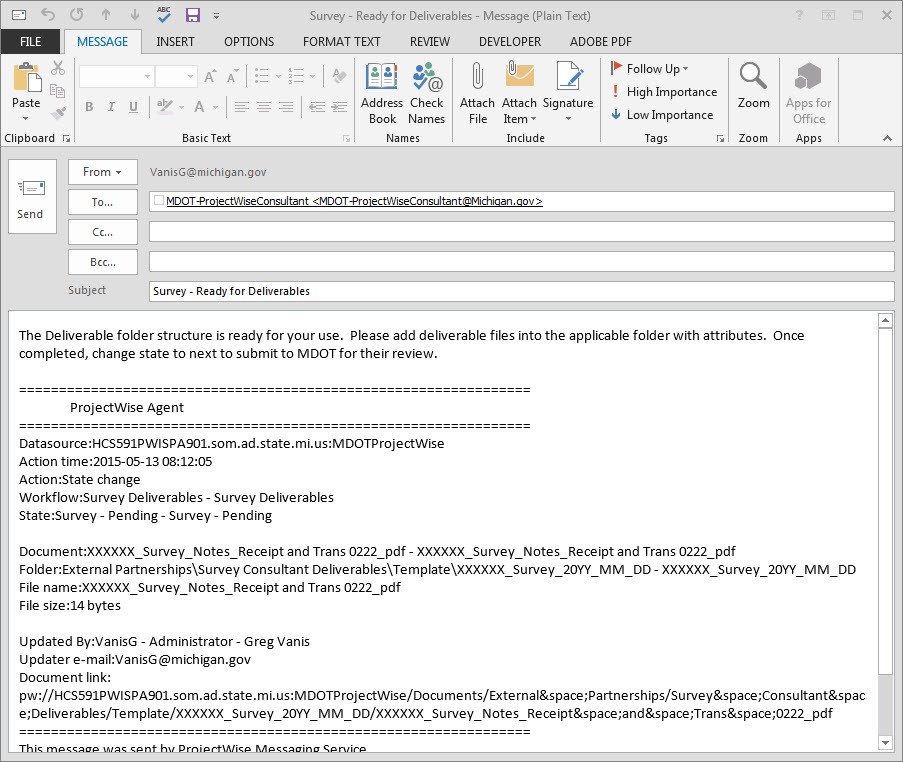 Figure 10.3.2 Email to Consultant informing that the folder is ready for the deliverables.
 - The consultant will then have access to the folder and will be able to place the required files and documents in the project folder in ProjectWise.
- When all the information is in ProjectWise the consultant will change the state to next on the Survey Notes Receipt and Transmittal form.
- This will trigger an automatic email which will be sent to the PM notifiying them that the project is ready for review.
- See Figure 10.3.3 for an example of the email.
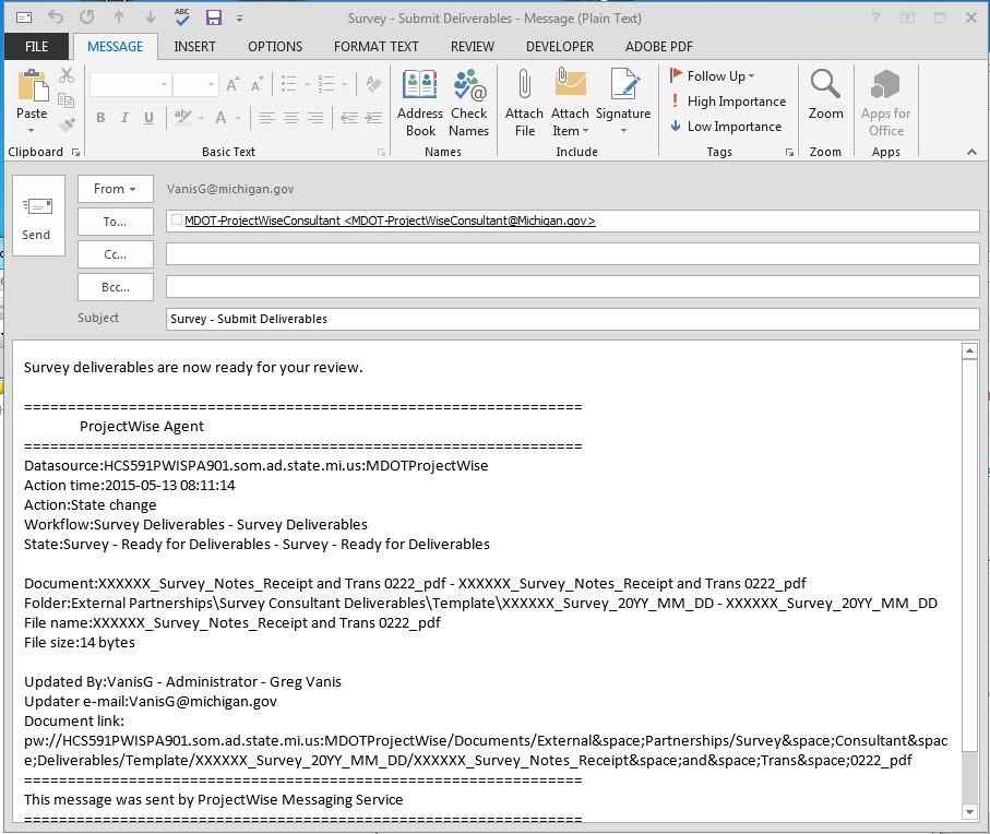 Figure 10.3.3 Email to PM informing that the deliverables are ready for review.
 - During the review process the consultant will still have access to add files if necessary.
- After the review process is complete the PM will change the state on the Survey Notes Receipt and Transmittal form to complete which will lock the folder and the data can then be moved from the consultant submittal folder to the appropriate project folder for the engineers to continue the design process.
- See Figure 10.3.4 for an example of the email.
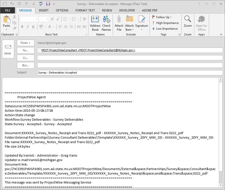 Figure 10.3.4 Email to Consultant informing that the deliverables have been accepted.


10.3.1 Media Requirements
- Software required for output submittal to MDOT includes the latest versions accepted by MDOT of the following (check the MDOT ftp website whose address is on Page 4 for the latest list):
- Bentley PowerGEOPAK (MDOT Current Version)
- Adobe Acrobat Professional
- Microsoft Word
- Approved horizontal least squares adjustment software: LGO (Leica Geomatics Office), TGO (Trimble Geo Office), TBC (Trimble Business Center), Starnet (Plus/Pro), MicroSurvey’s Starnet. Any other horizontal adjustment program will need prior approval for use on an MDOT project.
- Approved vertical least squares adjustment software: Levproc, Starlev (Starnet Pro), and MicroSurvey’s Starnet are the only vertical adjustment programs that are acceptable at this time. Any other vertical adjustment program will have to be presented for evaluation by MDOT.