File list
Jump to navigation
Jump to search
This special page shows all uploaded files.
| Date | Name | Thumbnail | Size | User | Description | Versions |
|---|---|---|---|---|---|---|
| 12:48, 19 May 2014 | Fig712.16.png (file) |  |
870 KB | HarrisR18 | 1 | |
| 12:47, 19 May 2014 | Fig712.15.png (file) |  |
1.74 MB | HarrisR18 | 1 | |
| 12:47, 19 May 2014 | Fig712.14.png (file) |  |
962 KB | HarrisR18 | 1 | |
| 12:46, 19 May 2014 | Fig712.13.png (file) |  |
442 KB | HarrisR18 | 1 | |
| 12:45, 19 May 2014 | Fig712.12.png (file) |  |
594 KB | HarrisR18 | 2 | |
| 12:44, 19 May 2014 | Fig712.9.png (file) |  |
818 KB | HarrisR18 | 1 | |
| 12:44, 19 May 2014 | Fig712.7.png (file) |  |
791 KB | HarrisR18 | 1 | |
| 12:43, 19 May 2014 | Fig712.6.png (file) |  |
429 KB | HarrisR18 | 1 | |
| 12:43, 19 May 2014 | Fig712.5.png (file) |  |
1.5 MB | HarrisR18 | 1 | |
| 12:42, 19 May 2014 | Fig712.4.png (file) |  |
109 KB | HarrisR18 | 1 | |
| 12:42, 19 May 2014 | Fig712.3.png (file) |  |
32 KB | HarrisR18 | 2 | |
| 09:50, 19 May 2014 | Cost maunal 712(21).png (file) | .png) |
58 KB | HarrisR18 | 1 | |
| 09:31, 19 May 2014 | Fig712.1.png (file) |  |
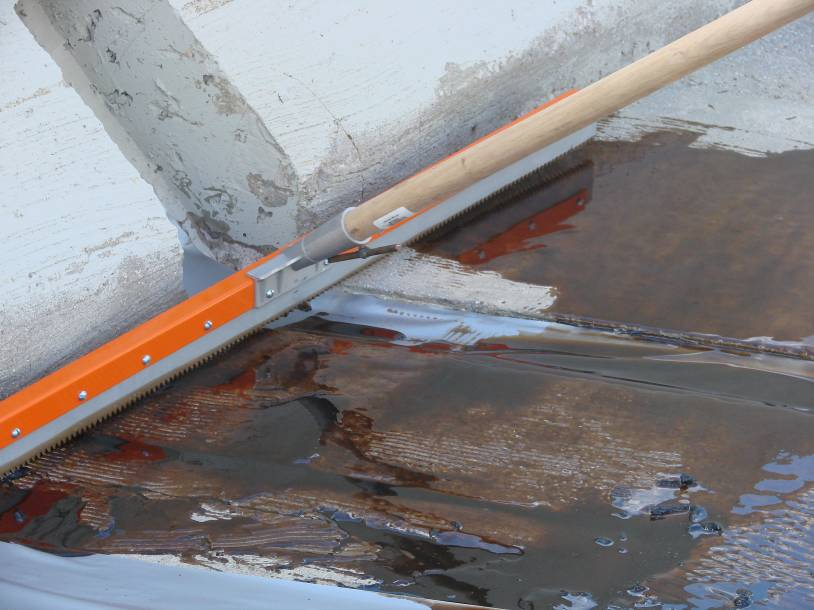
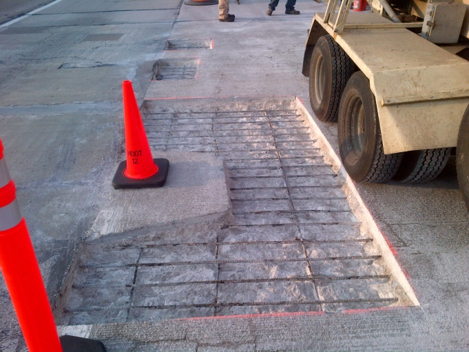
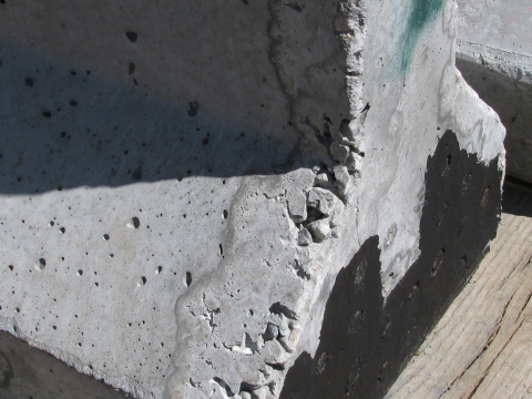
785 KB | HarrisR18 | Figure 712.1 Square the patch to avoid multiple corners as best as possible. | 1 |
| 12:59, 12 May 2014 | Fig 708-11.png (file) |  |
226 KB | Greenes2 | Figure 708-11 Crack comparator for measuring crack width | 1 |
| 12:58, 12 May 2014 | Fig 708.10.png (file) |  |
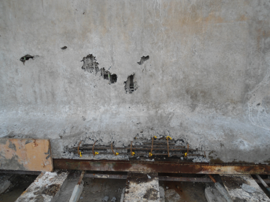
400 KB | Greenes2 | Figure 708.10 – Major deficiency – improper consolidation of concrete and expose prestressing strands and steel reinforcement | 1 |
| 12:58, 12 May 2014 | Fig 708.9.png (file) |  |
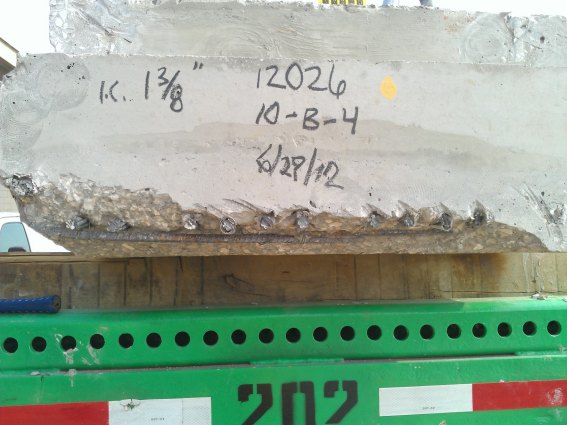
318 KB | Greenes2 | Figure 708.9 – Major deficiency – spalled bottom corner and exposed prestressing strands at the end of a box beam | 1 |
| 12:57, 12 May 2014 | Fig 708.8.png (file) |  |
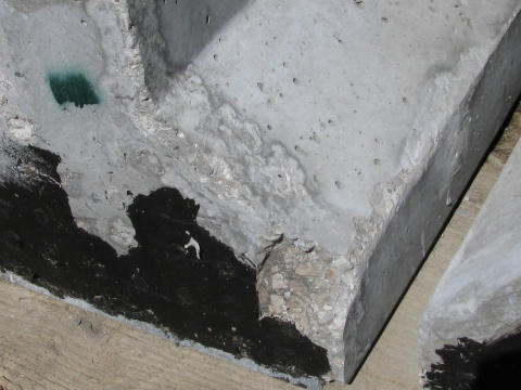
416 KB | Greenes2 | Figure 708.8 – Minor damage – spalled bottom corner at the end of a box beam | 1 |
| 12:57, 12 May 2014 | Fig 708.7.png (file) |  |
324 KB | Greenes2 | Figure 708.7 – Minor damage – broken corner at end of PCI girder | 1 |
| 12:56, 12 May 2014 | Fig 708.6.png (file) |  |
342 KB | Greenes2 | Figure 708.6 – Minor surface defect – honeycombing of PCI girder | 1 |
| 12:55, 12 May 2014 | Fig 708.5.png (file) |  |
350 KB | Greenes2 | Figure 708.5 – Minor surface defect – rubber gasket crease | 1 |
| 12:55, 12 May 2014 | Fig 708.4.png (file) |  |
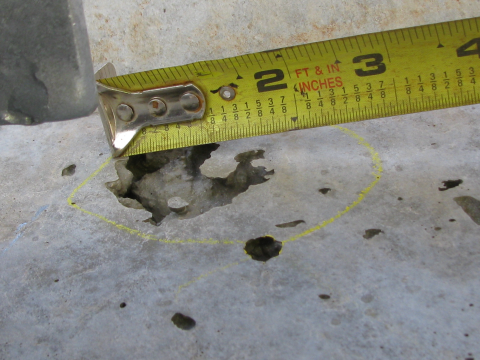
325 KB | Greenes2 | Figure 708.4 – Minor surface defect – air holes greater than 1” in any direction | 1 |
| 12:54, 12 May 2014 | Fig 708.3.png (file) |  |
870 KB | Greenes2 | Figure 708.3 – Structural Precast Concrete Fabrication Inspection Flowchart | 1 |
| 12:54, 12 May 2014 | Fig 708.2.png (file) |  |
147 KB | Greenes2 | Figure 708.2 | 1 |
| 12:53, 12 May 2014 | Fig 708.2-1.png (file) |  |
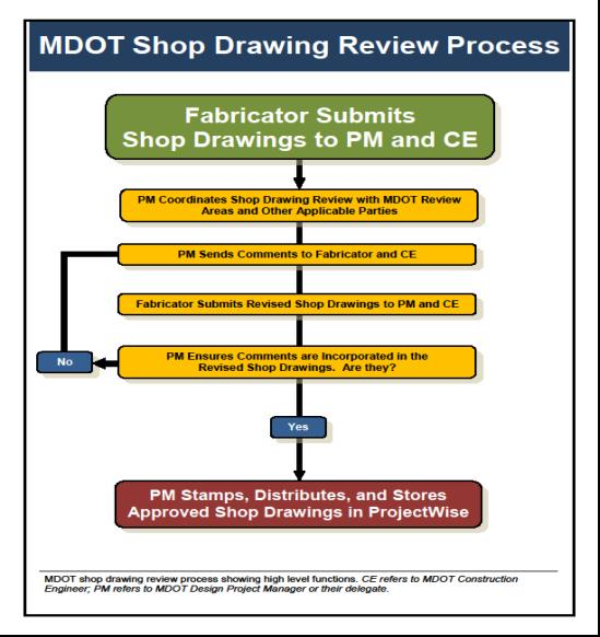
255 KB | Greenes2 | Figure 708.2-1 – Shop Drawing Review Process | 1 |
| 12:52, 12 May 2014 | Fig 708.1-1.png (file) |  |
223 KB | Greenes2 | Figure 708.1-1 – Shop Drawing Review Process | 1 |
| 08:57, 9 May 2014 | Petosky US31.png (file) |  |
1.07 MB | Greenes2 | Construction of US-31 in Petosky. | 1 |
| 08:52, 9 May 2014 | Mackinac Bridge.png (file) |  |
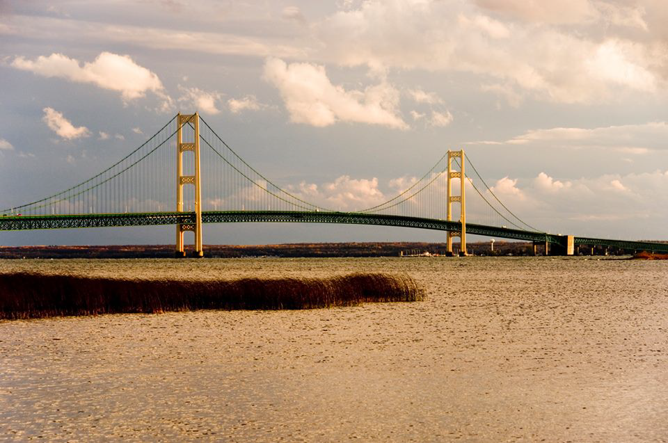
926 KB | Greenes2 | Construction began 60 years ago this month on the "Mighty Mac" | 1 |
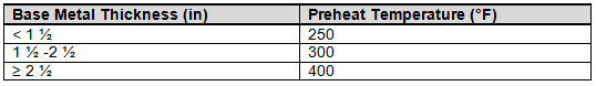
| 09:48, 2 May 2014 | Table707.6.png (file) | 4 KB | Greenes2 | Table 707.6 - Minimum Preheat Temperatures | 1 | |
| 09:48, 2 May 2014 | Fig707.13.png (file) |  |
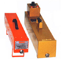
75 KB | Greenes2 | Figure 707.13 Hotboxes for Electrode Storage | 1 |
| 09:46, 2 May 2014 | Fig707.11.png (file) |  |
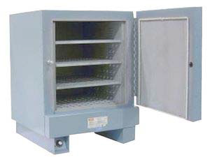
102 KB | Greenes2 | Figure 707.11 Drying and Storage Oven | 1 |
| 09:46, 2 May 2014 | Fig707.10.png (file) |  |
213 KB | Greenes2 | Figure 707.10 Sample Approved Weld Procedure Specification (WPS) | 1 |
| 09:45, 2 May 2014 | Table707.5.png (file) |  |
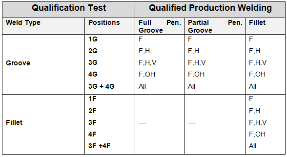
11 KB | Greenes2 | Table 707.5 Welder Qualification Type and Position Limitations | 1 |
| 09:44, 2 May 2014 | Fig707.9.png (file) |  |
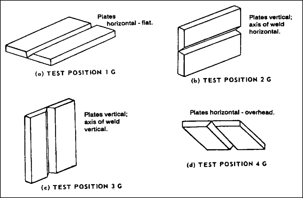
96 KB | Greenes2 | Figure 707.9 - Groove Weld (G) Position | 1 |
| 09:40, 2 May 2014 | Fig707.8.png (file) |  |
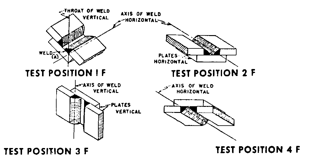
10 KB | Greenes2 | Figure 707.8 - Fillet Weld (F) Positions | 1 |
| 15:06, 1 May 2014 | Fig707.6.png (file) |  |
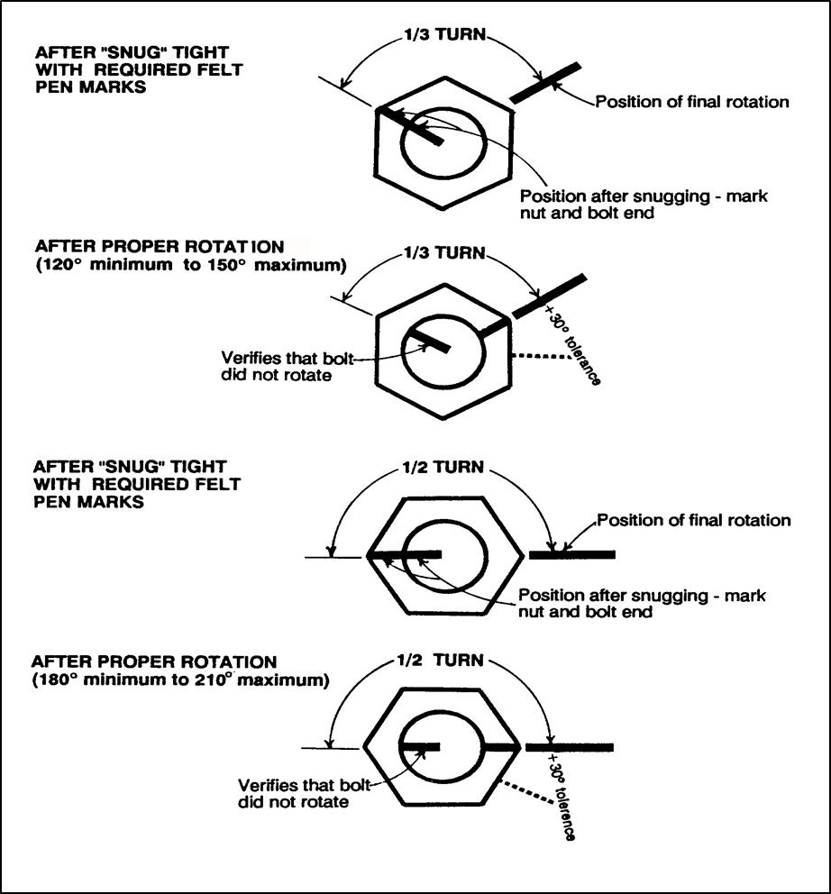
141 KB | Greenes2 | Figure 707.6 Typical Turn of Nut Marking System | 1 |
| 15:05, 1 May 2014 | Table707.4.png (file) |  |
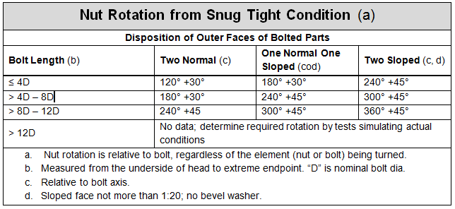
21 KB | Greenes2 | Nut Rotation from Snug Tight Condition | 1 |
| 14:50, 1 May 2014 | Table707.2.png (file) |  |
74 KB | Greenes2 | Brief description of high strength bolts, nuts and washers used for structural applications. | 1 |
| 14:38, 1 May 2014 | Fig707.5.png (file) |  |
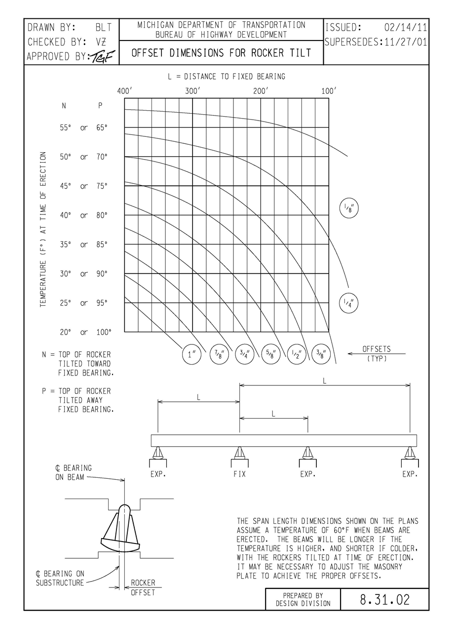
261 KB | Greenes2 | Figure 707.5 Offset Dimension for Rocker Tilt | 1 |
| 13:30, 1 May 2014 | Fig707.3.png (file) |  |
260 KB | Greenes2 | Figure 707.3 - Steel Fabrication Inspection Flowchart | 1 |
| 13:29, 1 May 2014 | Fig707.2.png (file) |  |
147 KB | Greenes2 | Figure 707.2 Approved For Use Stamp (MDOT) | 1 |
| 13:27, 1 May 2014 | Fig707.1-2.png (file) |  |
255 KB | Greenes2 | Figure 707.1-2 Shop Drawing Review Process | 1 |
| 13:24, 1 May 2014 | Fig707.1-1.png (file) |  |
223 KB | Greenes2 | Figure 707.1-1 – Shop Drawing Review Process | 1 |
| 11:18, 1 May 2014 | Fig604-03.png (file) |  |
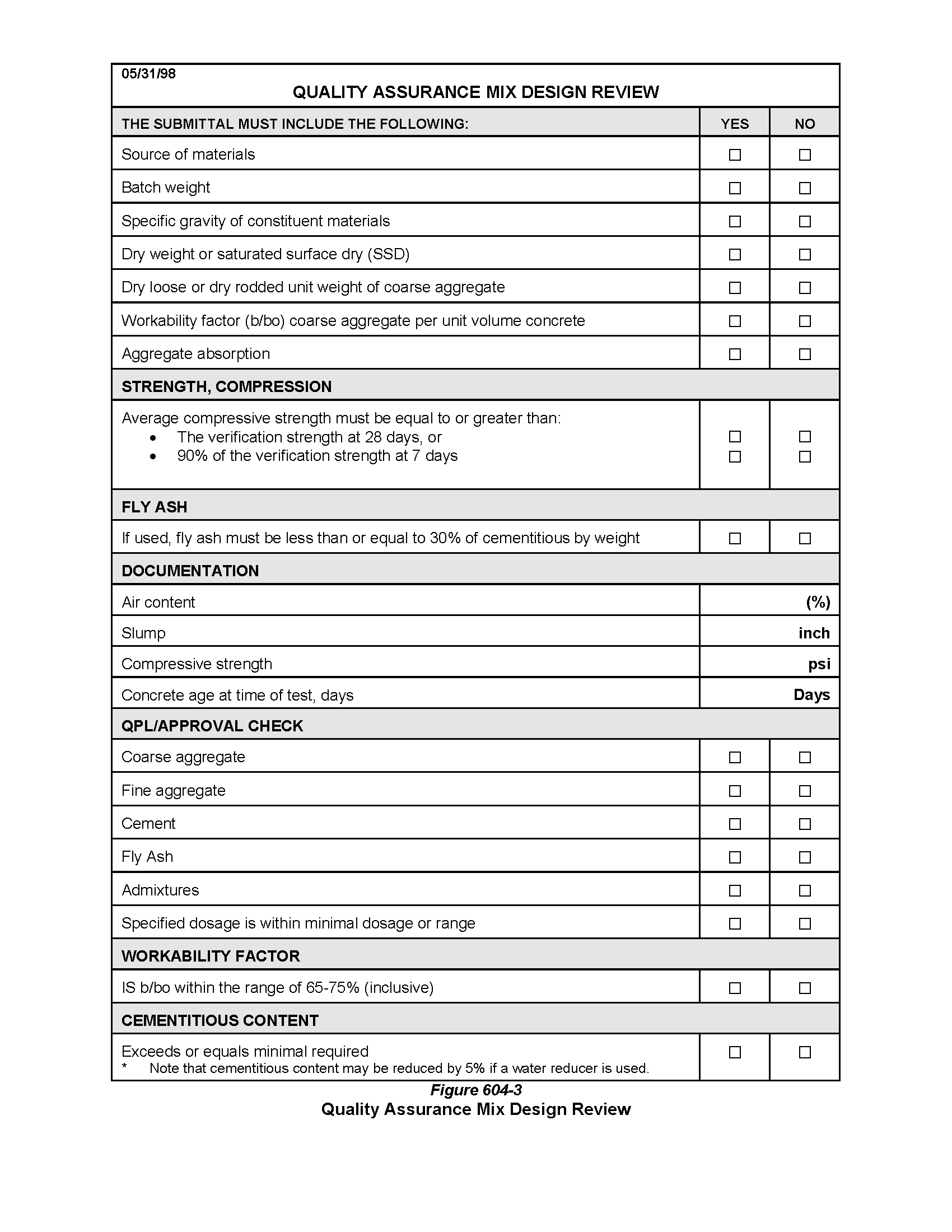
37 KB | Greenes2 | Figure 604-3: Quality Assurance Mix Design Review | 1 |
| 11:11, 1 May 2014 | Fig604-02.png (file) |  |
64 KB | Greenes2 | MDOT Checklist For Concrete Paving With Warranty | 1 |
| 12:22, 29 April 2014 | Table603-01.png (file) |  |
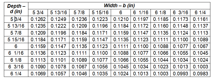
26 KB | Greenes2 | Table 1: Modulus of Rupture Factors (F) | 1 |
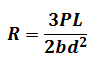
| 12:17, 29 April 2014 | EQ 603-02.png (file) |  |
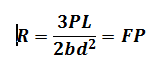
2 KB | Greenes2 | Simplified Center Point Flexural Strength Equation | 1 |
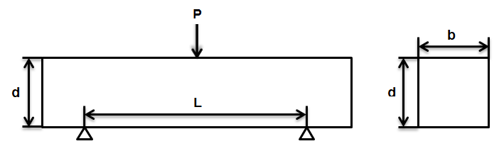
| 12:15, 29 April 2014 | FIG603-01.png (file) |  |
10 KB | Greenes2 | Beam Measurements | 1 |
| 12:11, 29 April 2014 | EQ603-01.png (file) |  |
1 KB | Greenes2 | Flexural Strength of Concrete (Using Simple Beam With Center Point Loading): | 1 |
| 08:17, 29 April 2014 | %Ret Table Check 4-24-13.xls (file) | 132 KB | Greenes2 | Percent Retained Table Check 04-24-13 | 1 | |
| 08:15, 29 April 2014 | Concrete JMF Yield Calculator.v3.4-17-13.xls (file) | 30 KB | Greenes2 | Concrete JMF Yield Calculator v3 04-17-13 | 1 |