Uploads by Greenes2
Jump to navigation
Jump to search
This special page shows all uploaded files.
| Date | Name | Thumbnail | Size | Description | Versions |
|---|---|---|---|---|---|
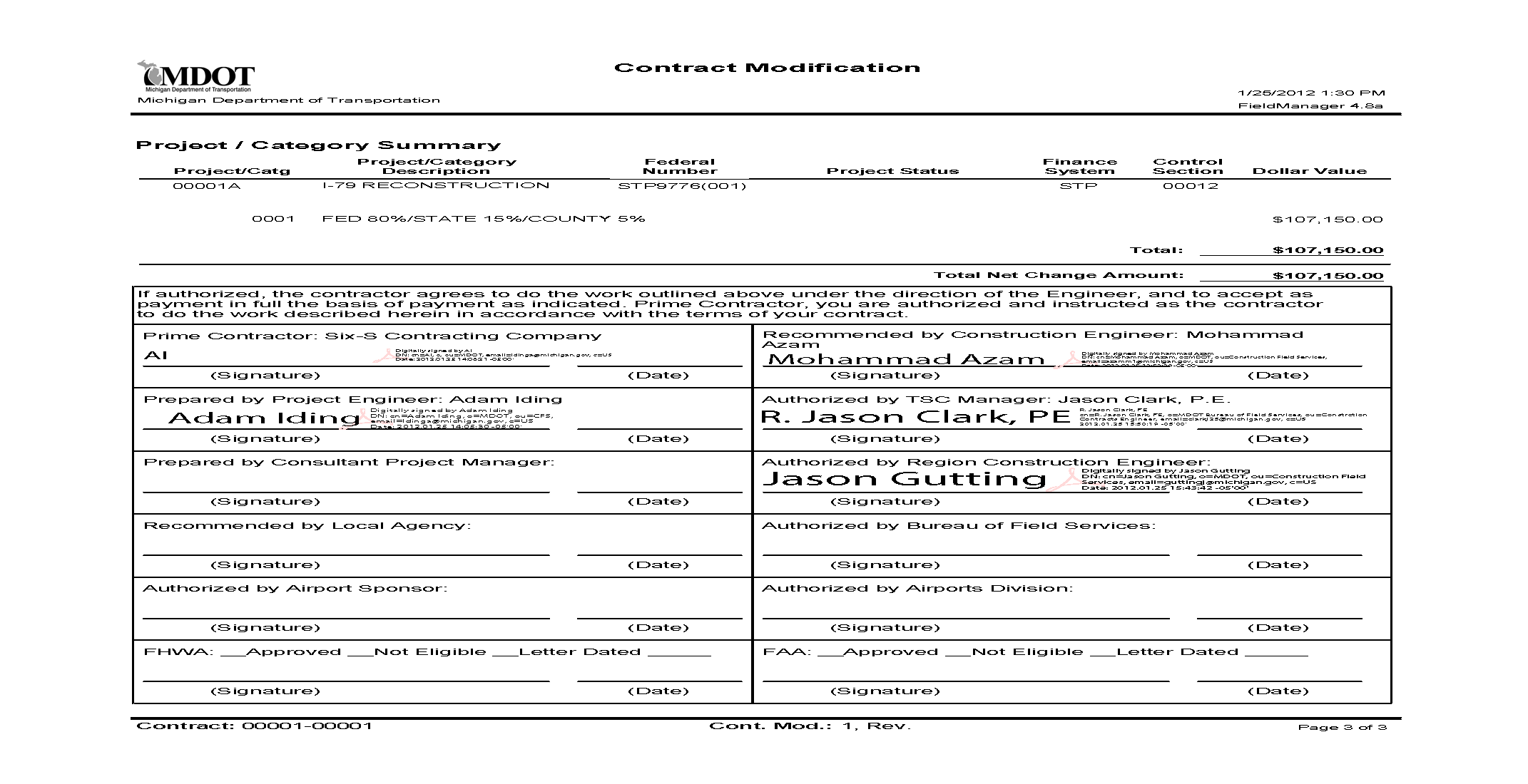
| 14:17, 17 June 2014 | Appendix B - Sample Contract Modification.pdf (file) | 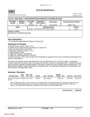 |
229 KB | Sample Contract Modification | 1 |
| 09:56, 24 November 2015 | Auburn Hills DDI.jpg (file) |  |
443 KB | 1 | |
| 16:10, 24 November 2015 | BridgeslideM100.jpg (file) |  |
463 KB | 1 | |
| 08:15, 29 April 2014 | Concrete JMF Yield Calculator.v3.4-17-13.xls (file) | 30 KB | Concrete JMF Yield Calculator v3 04-17-13 | 1 | |
| 15:20, 16 September 2014 | Construction Guidance for Pavement Marking Projects.pdf (file) | 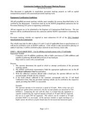 |
104 KB | 1 | |
| 08:51, 25 June 2014 | Crews recently removed bridge beams from M-47 over US-10 near Midland.png (file) |  |
230 KB | Crews recently removed bridge beams from M-47 over US-10 near Midland | 1 |
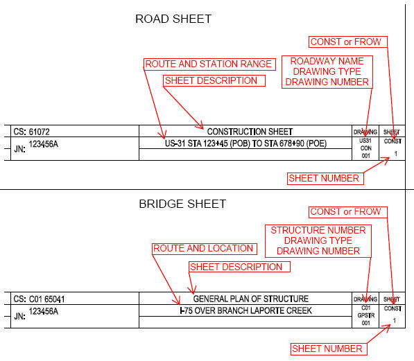
| 08:57, 28 June 2013 | DU Title Block image.jpg (file) |  |
71 KB | 1 | |
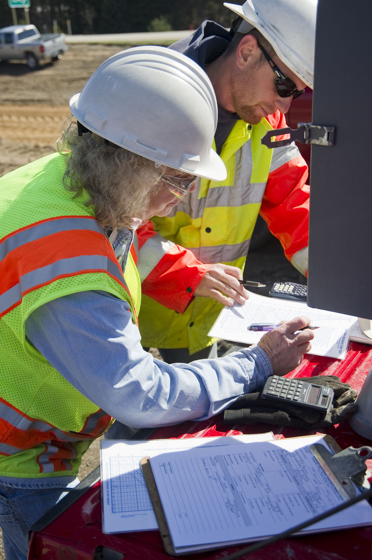
| 09:37, 1 October 2013 | Density Inspection.jpg (file) |  |
374 KB | 1 | |
| 15:26, 30 May 2014 | DownTown Detroit Panorama.png (file) | 280 KB | Downtown Detorit Panorama at the Monument to Joe Louis | 1 | |
| 15:27, 7 August 2014 | E-sign brochure.pdf (file) | 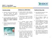 |
184 KB | E-sign brochure | 1 |
| 12:11, 29 April 2014 | EQ603-01.png (file) |  |
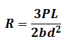
1 KB | Flexural Strength of Concrete (Using Simple Beam With Center Point Loading): | 1 |
| 12:17, 29 April 2014 | EQ 603-02.png (file) |  |
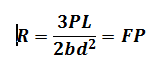
2 KB | Simplified Center Point Flexural Strength Equation | 1 |
| 09:50, 2 July 2014 | ExCMpg1.png (file) |  |
55 KB | Example Contract Modification Page 1 | 1 |
| 09:50, 2 July 2014 | ExCMpg2.png (file) |  |
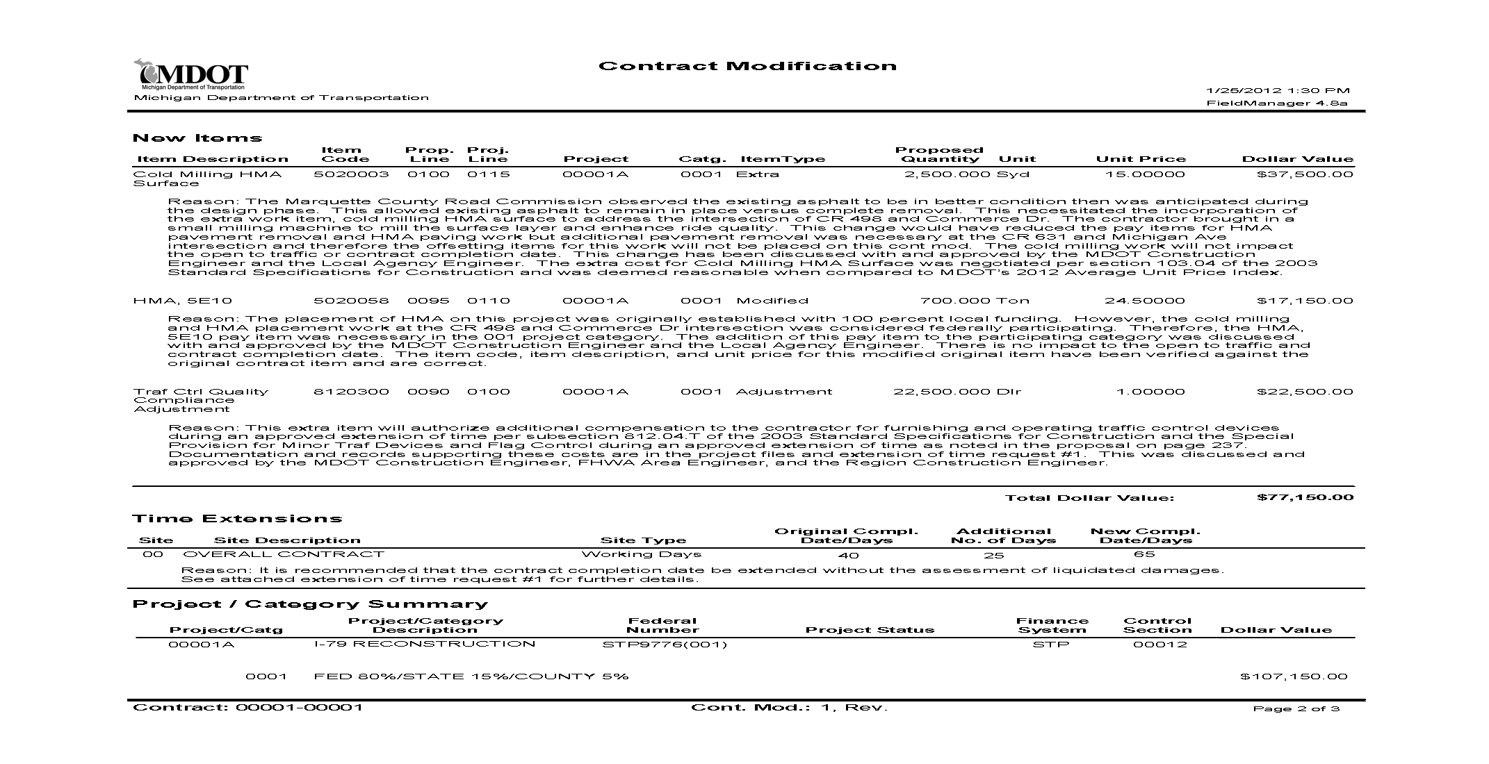
68 KB | Example Contract Modification Page 2 | 1 |
| 09:51, 2 July 2014 | ExCMpg3.png (file) |  |
53 KB | Example Contract Modification Page 3 | 1 |
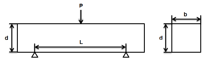
| 12:15, 29 April 2014 | FIG603-01.png (file) |  |
10 KB | Beam Measurements | 1 |
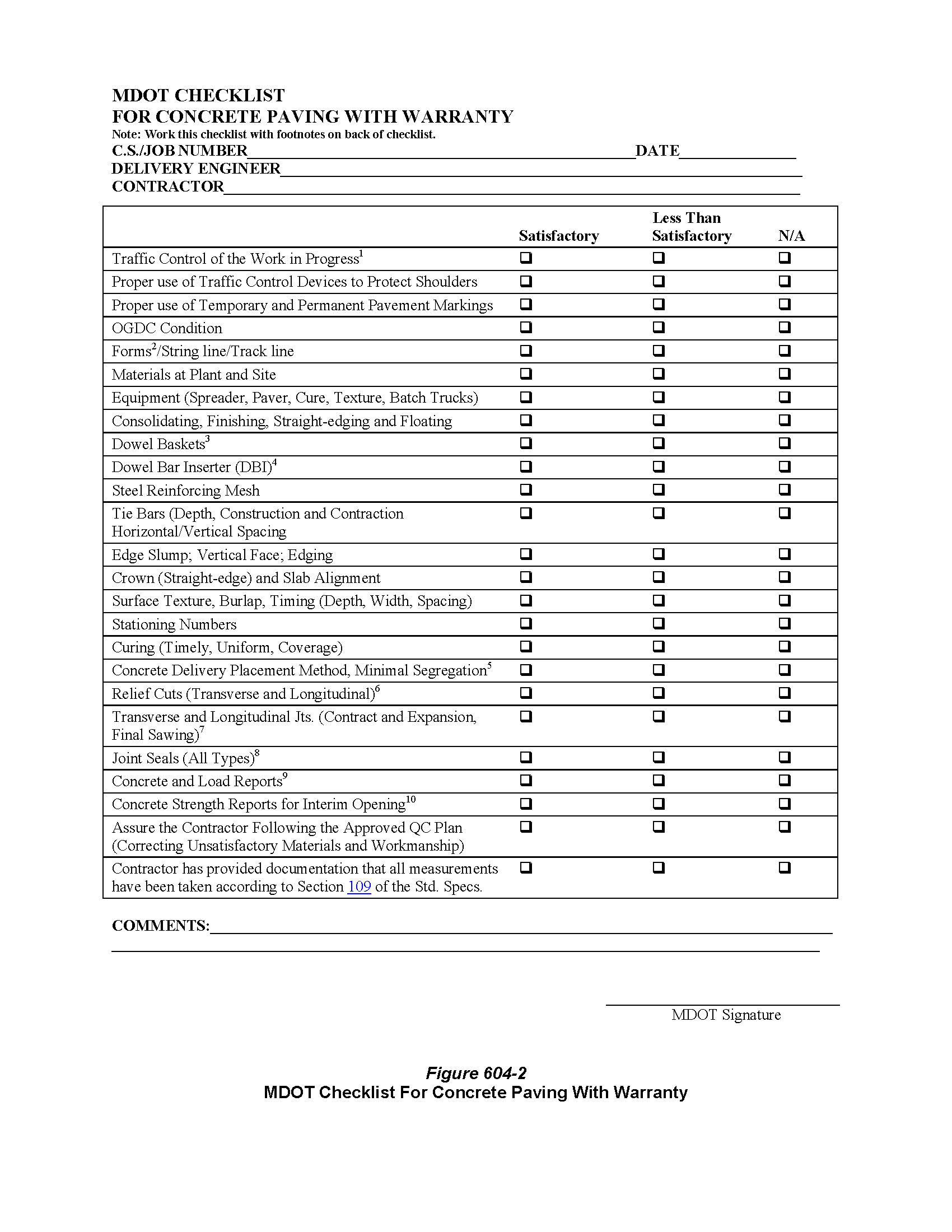
| 11:11, 1 May 2014 | Fig604-02.png (file) |  |
64 KB | MDOT Checklist For Concrete Paving With Warranty | 1 |
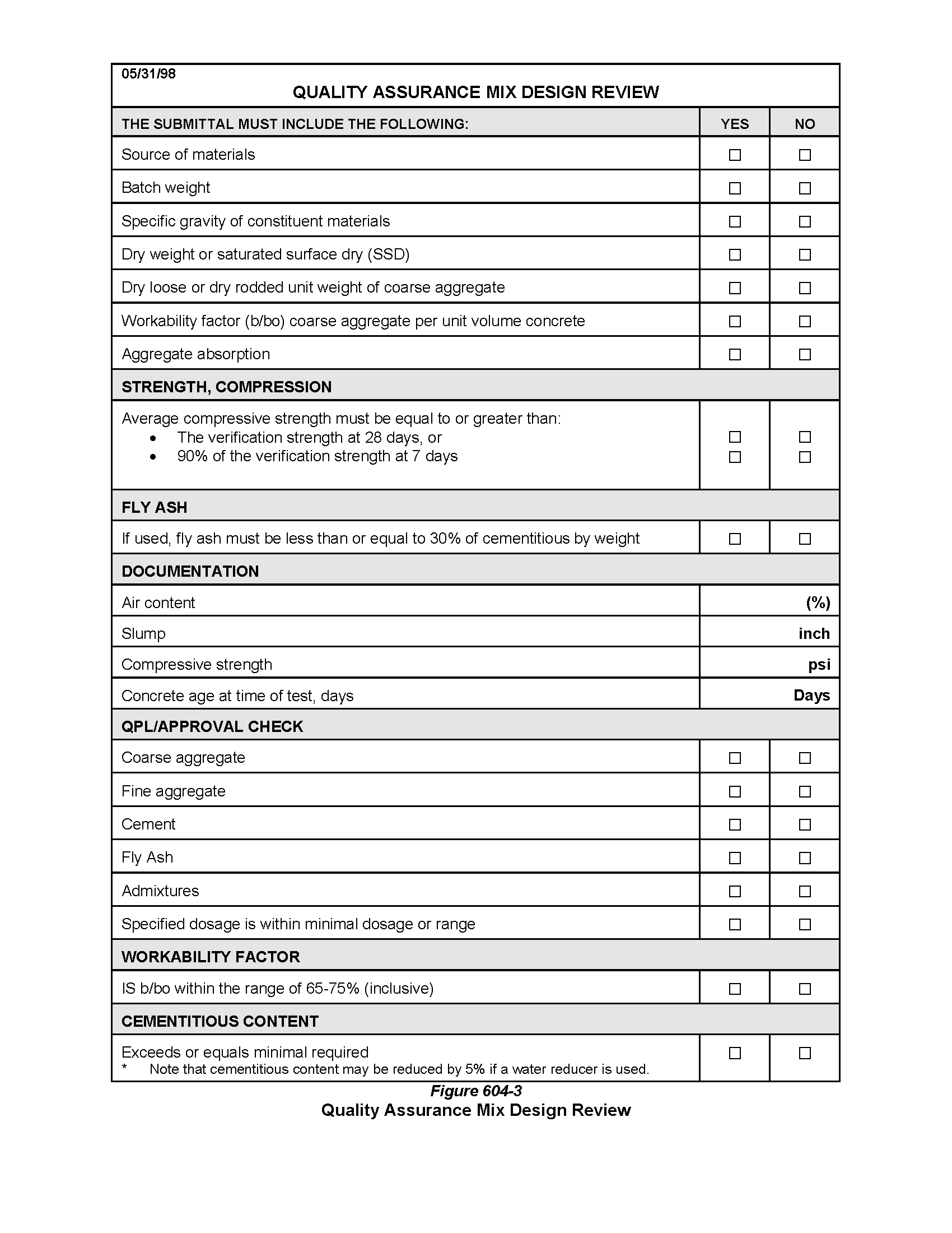
| 11:18, 1 May 2014 | Fig604-03.png (file) |  |
37 KB | Figure 604-3: Quality Assurance Mix Design Review | 1 |
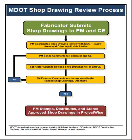
| 13:24, 1 May 2014 | Fig707.1-1.png (file) |  |
223 KB | Figure 707.1-1 – Shop Drawing Review Process | 1 |
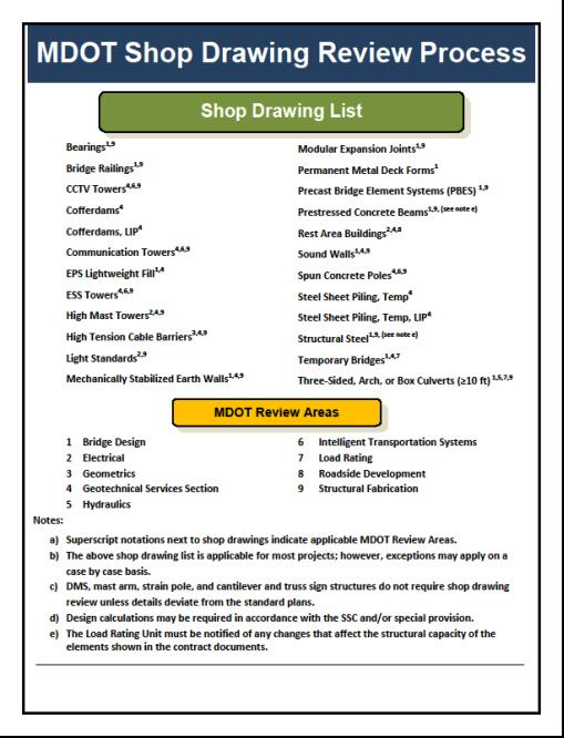
| 13:27, 1 May 2014 | Fig707.1-2.png (file) |  |
255 KB | Figure 707.1-2 Shop Drawing Review Process | 1 |
| 09:46, 2 May 2014 | Fig707.10.png (file) |  |
213 KB | Figure 707.10 Sample Approved Weld Procedure Specification (WPS) | 1 |
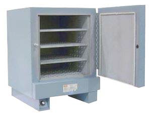
| 09:46, 2 May 2014 | Fig707.11.png (file) |  |
102 KB | Figure 707.11 Drying and Storage Oven | 1 |
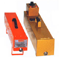
| 09:48, 2 May 2014 | Fig707.13.png (file) |  |
75 KB | Figure 707.13 Hotboxes for Electrode Storage | 1 |
| 13:29, 1 May 2014 | Fig707.2.png (file) |  |
147 KB | Figure 707.2 Approved For Use Stamp (MDOT) | 1 |
| 13:30, 1 May 2014 | Fig707.3.png (file) |  |
260 KB | Figure 707.3 - Steel Fabrication Inspection Flowchart | 1 |
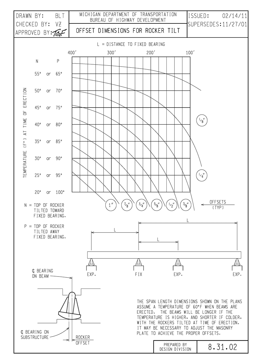
| 14:38, 1 May 2014 | Fig707.5.png (file) |  |
261 KB | Figure 707.5 Offset Dimension for Rocker Tilt | 1 |
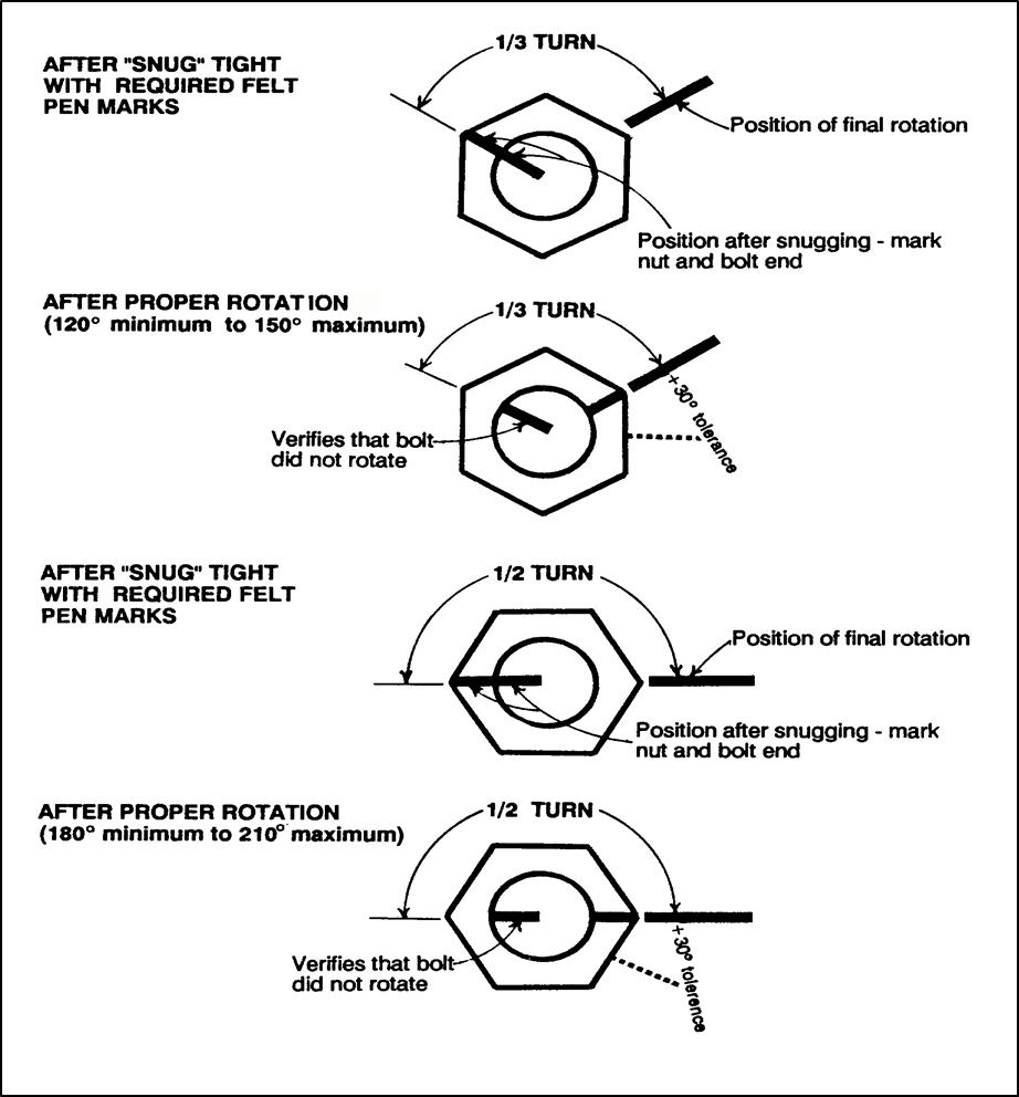
| 15:06, 1 May 2014 | Fig707.6.png (file) |  |
141 KB | Figure 707.6 Typical Turn of Nut Marking System | 1 |
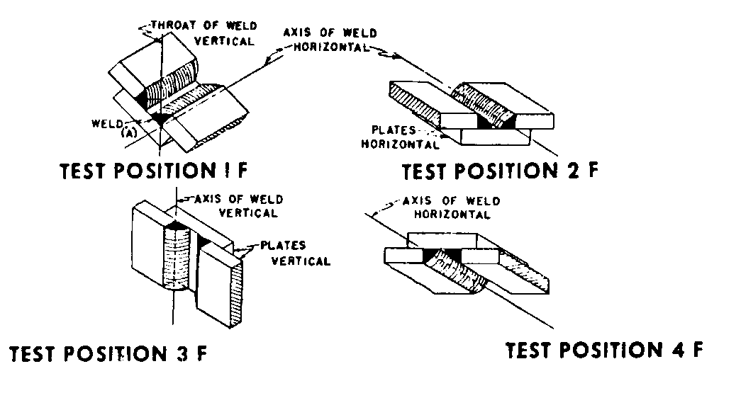
| 09:40, 2 May 2014 | Fig707.8.png (file) |  |
10 KB | Figure 707.8 - Fillet Weld (F) Positions | 1 |
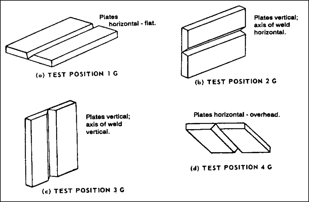
| 09:44, 2 May 2014 | Fig707.9.png (file) |  |
96 KB | Figure 707.9 - Groove Weld (G) Position | 1 |
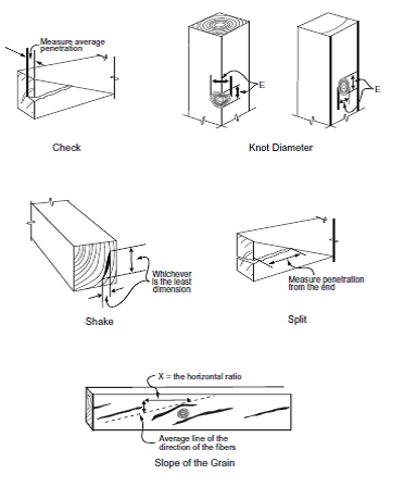
| 08:06, 9 April 2014 | Fig709-01.png (file) |  |
40 KB | Timber and Lumber Terminology | 1 |
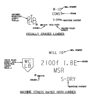
| 08:06, 9 April 2014 | Fig709-02.png (file) |  |
19 KB | Typical Lumber Grading Marks | 1 |
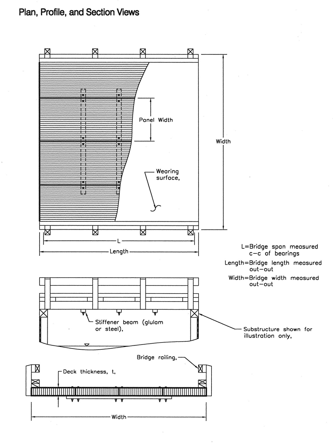
| 08:11, 9 April 2014 | Fig709-03.png (file) |  |
518 KB | Stress laminated deck system showing typical components. USDA-FPL-GTR-125 | 1 |
| 08:12, 9 April 2014 | Fig709-04.png (file) |  |
23 KB | Inspection Stamp for Glulam Lumber | 1 |
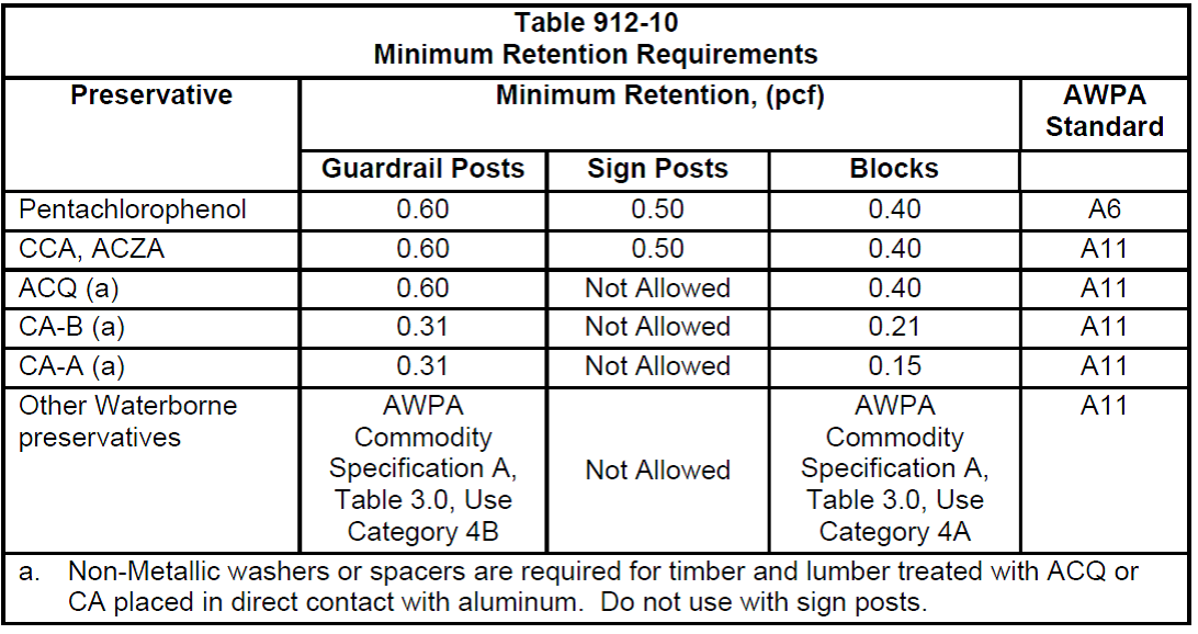
| 08:14, 9 April 2014 | Fig709-05.png (file) |  |
161 KB | Table 912-10 Preservation retention requirements. MDOT 2012 Standard Specifications for Construction. | 1 |
| 08:15, 9 April 2014 | Fig711-01.png (file) |  |
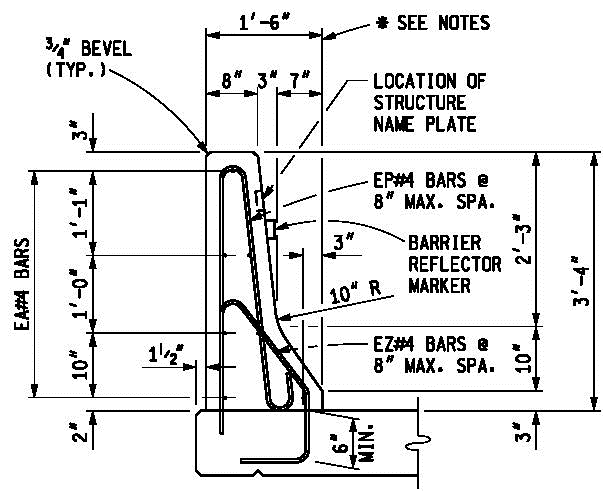
30 KB | Bridge Barrier Railing Type 4 | 1 |
| 08:16, 9 April 2014 | Fig711-02.png (file) |  |
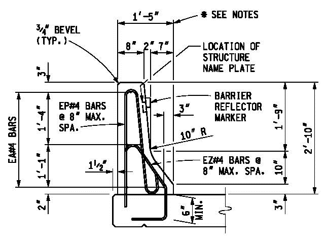
28 KB | Bridge Barrier Railing Type 5 | 1 |
| 08:16, 9 April 2014 | Fig711-03.png (file) |  |
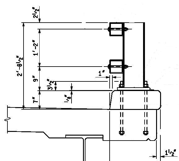
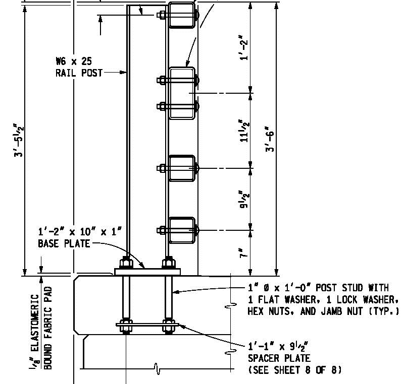
52 KB | Bridge Barrier Railing, 2 Tube | 1 |
| 08:17, 9 April 2014 | Fig711-04.png (file) |  |
41 KB | Bridge Barrier Railing, 4 Tube | 1 |
| 08:18, 9 April 2014 | Fig711-05.png (file) |  |
17 KB | Bridge Barrier Railing, Thrie Beam REtorfit (R4 Type Bridge Railing) | 1 |
| 08:19, 9 April 2014 | Fig711-06.png (file) |  |
28 KB | Bridge Barrier Railing, Thrie Beam Retrofit (Open Parapet Type Bridge Railing) | 1 |
| 08:20, 9 April 2014 | Fig711-07.png (file) |  |
110 KB | Bridge Barrier Railing, Aesthetic Parapet Tube | 1 |
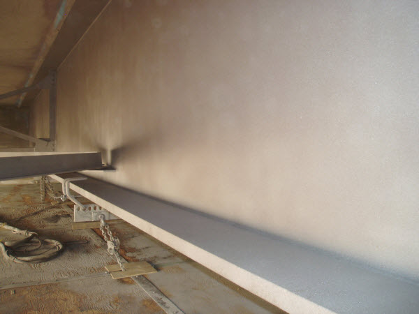
| 08:01, 9 July 2014 | Fig715-02.jpg (file) |  |
33 KB | Figure 715-02 Near white blasted steel surface (SSPC-SP10). | 1 |
| 08:21, 9 April 2014 | Fig717-01.png (file) |  |
154 KB | Drain Casting Assembly Details from Standard Plan Series B101 | 1 |
| 13:35, 19 March 2014 | Fig 602-05.png (file) |  |
39 KB | Figure 602-5 Positioning Dowel Basket Assemblies | 1 |
| 13:36, 19 March 2014 | Fig 602-06.png (file) |  |
47 KB | Figure 602-6 Basket Pin and Basket Level | 1 |
| 13:36, 19 March 2014 | Fig 602-07.png (file) |  |
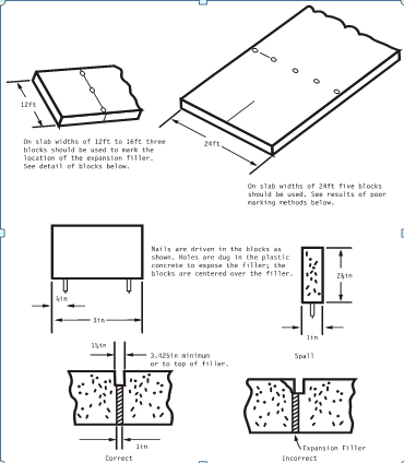
40 KB | Figure 602-7 Transverse Expansion Joints | 1 |
| 13:37, 19 March 2014 | Fig 602-08.png (file) |  |
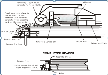
33 KB | Figure 602-8 Header Board Placement | 1 |
| 16:30, 29 January 2014 | Fig 704-8.png (file) |  |
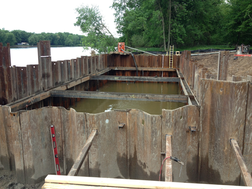
1.21 MB | Figure 704-8: Typical cofferdam bracing with walers and struts | 1 |
| 12:14, 3 February 2014 | Fig 705-1.png (file) |  |
8 KB | Figure 1. Typical HP shape | 1 |
| 12:15, 3 February 2014 | Fig 705-2.png (file) |  |
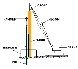
22 KB | Figure 2. Typical pile driving equipment set up | 1 |